Introduction
Shunt capacitors, connected between line and neutral or line and ground, are common sights on power systems. They may be there to correct a lagging power factor or in cases, to provide voltage support for the system.
The transient current that occurs when the capacitor bank is energized can be significantly higher than its rated current. In this case, the frequency of the transient can reach a few kilohertz.
The frequency, peak, and rate of change (i.e. di/dt) of the current must be controlled in order to ensure that the circuit breaker can withstand the capacitor energizing currents, without sustaining damage.
In some applications they are switched in and out quite frequently as the system load varies and the system voltage fluctuates. It will be shown that such switching operations are nontrivial and should be carefully considered when designing capacitor banks and their associated switching equipment.
Purpose
The purpose of this study is to illustrate key points that need to be considered when the capacitor bank is energized. In general, energizing a capacitor gives rise to fast transients.
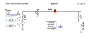
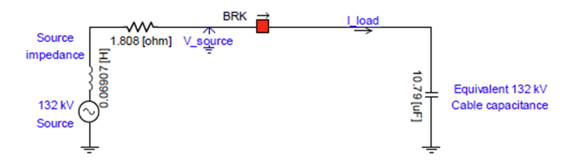
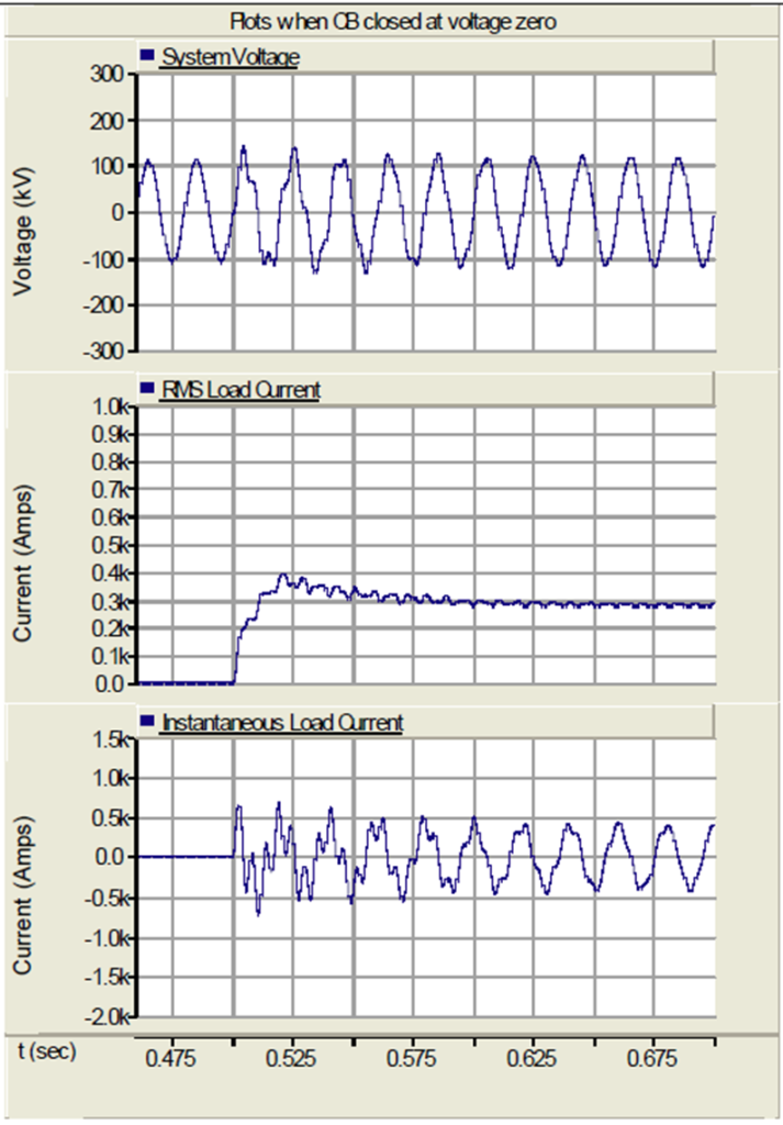
When capacitor is closed on to a source voltage with inductive source internal reactance as shown in the model below, the current drawn by the capacitor will be directly dependent on the instantaneous voltage at which it was closed. If CB/switch is closed at voltage zero crossing, the capacitor current will smoothly rise from zero.
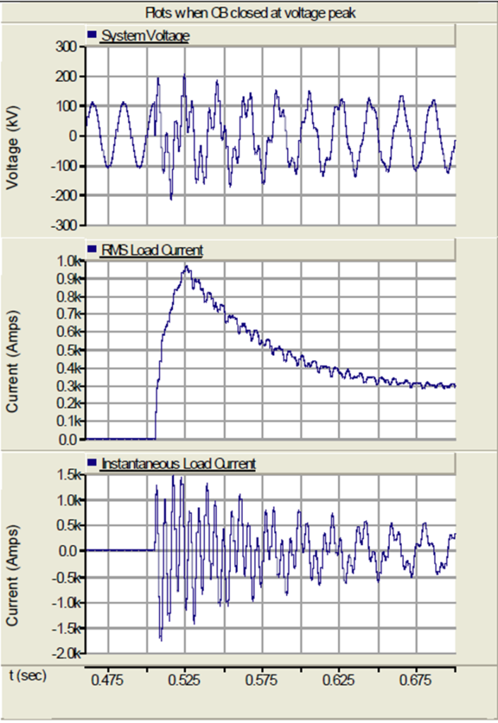
When CB is closed at peak of voltage, the inrush current will be high. This high capacitive current through the source inductive internal reactance can result in high transient switching over voltages. (High capacitive leading current across source inductance will cause voltage rise across capacitance).
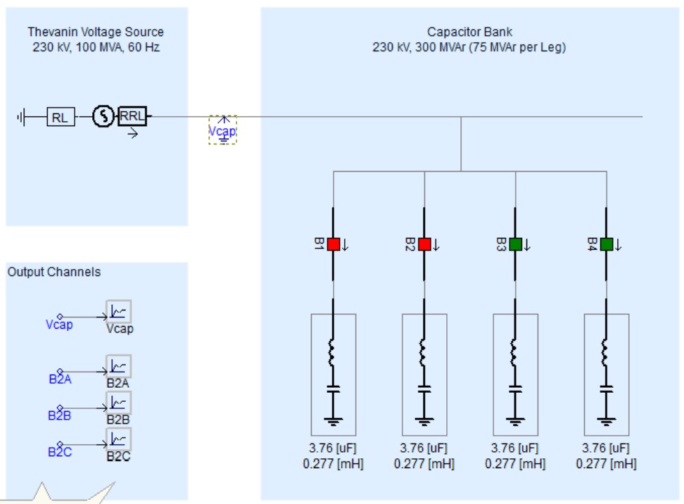
Modelling Capacitive Circuit in PSCAD
Results of Capacitive Circuit Energization
Result of capacitive circuit energizing at zero instant of system voltage:
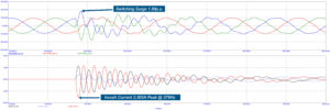
Result of capacitive circuit energizing at peak instant of system voltage:
Conclusion
The above analysis concludes that point of switching on the voltage wave plays an important role in generation of transient over voltages and over currents.
Switching ON the capacitor at peak of voltage wave causes high capacitive inrush current and highest over voltages. On the other hand, switching ON the capacitor at zero point of voltage wave causes lowest inrush current & lowest over voltages.