Applications of Power System Analysis is very important for the planning, design, and operation of industrial and commercial power systems.
This requires engineering studies to evaluate existing and proposed system performance, reliability, safety, and economics.
Studies, properly conceived and conducted, are a cost-effective way to prevent surprises and to optimize equipment selection.
In the design stage, the studies identify and avoid potential deficiencies in the system before it goes into operation.
In existing systems, the studies help locate the cause of equipment failure and mis-operation. It also determines corrective measures for improving system performance.
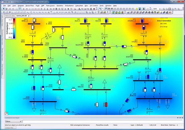
Load Flow Analysis
The studies determine the voltage, current, active, and reactive power and power factor in a power system. Load flow studies are an excellent tool for system planning.
The studies can be used to determine the optimum size and location of capacitors for power factor improvement. Also, they are very useful in determining system voltages under conditions of suddenly applied or disconnected loads.
The results of a load flow study are also starting points for stability studies. Digital computers are used extensively in load flow studies due to the complexity of the calculations involved.
Short Circuit Analysis
Short-circuit studies help to determine the magnitude of the fault currents flowing throughout the power system at various time intervals.
The magnitude of the currents after a fault vary with time until they reach a steady-state condition. This behavior is due to system characteristics and dynamics.
This is done for various types of faults (three-phase, phase-to-phase, double-phase-to-ground, and phase-to-ground) at different locations throughout the system.
The information is used to select fuses, breakers, and switchgear ratings in addition to setting protective relays.
Stability Analysis
The ability of a power system (two or more synchronous machines) to operate after a change on the system is a measure of its stability.
The stability problem takes two forms: steady-state and transient.
Steady-state stability is the ability of a power system to maintain synchronism between machines following relatively slow load changes.
Transient stability is the ability of the system to remain in synchronism under transient conditions, i.e., faults, switching operations, etc.
In an industrial power system, stability may involve the power company system and one or more in-plant generators or synchronous motors.
Contingencies, such as load rejection, sudden loss of a generator or utility tie, starting of large motors or faults, have a direct impact on system stability.
Load-shedding schemes and critical fault-clearing times can be determined in order to select the proper settings for protective relays.
These types of studies are probably the single most complex ones done on a power system.
A simulation will include synchronous generator models with their controls, i.e., voltage regulators, excitation systems, and governors.
Motors are sometimes represented by their dynamic characteristics as are static var compensators and protective relays.
Motor Starting Analysis
The starting current of most ac motors is several times normal full load current.
Both synchronous and induction motors can draw five to ten times full load current when starting them across the line.
Motor-starting torque varies directly as the square of the applied voltage. If the terminal voltage drop is excessive, the motor may not have enough starting torque to accelerate up to running speed.
Running motors may stall from excessive voltage drops, or undervoltage relays may operate.
In addition, if the motors are started frequently, the voltage dip at the source may cause objectionable flicker in the lighting system.
By using motor-starting study techniques, these problems can be predicted before the installation of the motor.
Harmonic Analysis
A harmonic-producing load can affect other loads if significant voltage distortion is caused.
The voltage distortion caused by the harmonic-producing load is a function of both the system impedance and the amount of harmonic current injected.
The mere fact that a given load current is distorted does not always mean there will be undue adverse effects on other power consumers.
If the system impedance is low, the voltage distortion is usually negligible in the absence of harmonic resonance.
However, if harmonic resonance prevails, intolerable harmonic voltage and currents are likely to result.
Some of the primary effects of voltage distortion are the following:
- Control/computer system interference
- Heating of rotating machinery
- Overheating/failure of capacitors
When the harmonic currents are high and travel in a path with significant exposure to parallel communication circuits, the principal effect is telephone interference.
This problem depends on the physical path of the circuit as well as the frequency and magnitude of the harmonic currents.
Harmonic currents also cause additional line losses and additional stray losses in transformers.
At harmonic frequencies, the meter may register high or low depending on the harmonics present and the response of the meter to these harmonics. Fortunately, the error is usually small.
The general procedure is to first develop a model that can accurately simulate the harmonic response of the present system and then to add a model of the new addition.
Analysis is also commonly done to evaluate alternatives for correcting problems found by measurements.
Switching Transient Analysis
Switching transients severe enough to cause problems in industrial power systems are most often associated with inadequate or malfunctioning breakers or switches and the switching of capacitor banks and other frequently switched loads.
The arc furnace system is most frequently studied because of its high frequency of switching and the related use of capacitor banks.
This study can analyze other system anomalies, such as lightning arrester operation, ferro-resonance, virtual current chopping, and breaker transient recovery voltage.
Reliability Analysis
When comparing various industrial power system design alternatives, acceptable system performance quality factors (including reliability) and cost are essential in selecting an optimum design.
A reliability index is the probability that a device will function without failure over a specified time period. This probability is determined by equipment maintenance requirements and failure rates.
Using probability and statistical analyses, the reliability of a power system can be studied in depth with digital computer programs.
Reliability is most often expressed as the frequency of interruptions and expected number of hours of interruptions during one year of system operation.
Momentary and sustained system interruptions, component failures, and outage rates are used in some reliability programs to compute overall system reliability indexes at any node in the system, and to investigate sensitivity of these indexes to parameter changes.
With these results, economics and reliability can be considered to select the optimum power system design.
Cable Ampacity Analysis
Cable ampacity studies calculate the current-carrying capacity (ampacity) of power cables in underground or above ground installations.
This ampacity is determined by the maximum allowable conductor temperature.
In turn, this temperature is dependent on the losses in the cable, both I2R and dielectric, and thermal coupling between heat-producing components and ambient temperature.
The ampacity calculations are extremely complex. This is due to many considerations, some examples of which are heat transfer through the cable insulation and sheath, and, in the case of underground installations, heat transfer to duct or soil as well as from duct bank to soil.
Other considerations include the effects of losses caused by proximity and skin effects. In addition, depending on the installation, the cable-shielding system may introduce additional losses.
The analysis involves the application of thermal equivalents of Ohm’s and Kirchhoff’s laws to a thermal circuit.
Ground Grid Analysis
Under ground-fault conditions, the flow of current will result in voltage gradients within and around the substation. This does not happen only between structures and nearby earth, but also along the ground surface.
In a properly designed system, this gradient should not exceed the limits that can be tolerated by the human body.
The purpose of a ground mat study is to provide for the safety and well-being of anyone that can be exposed to the potential differences that can exist in a station during a severe fault.
The general requirements for industrial power system grounding are similar to those of utility systems under similar service conditions.
The differences arise from the specific requirements of the manufacturing or process operations.
Some of the factors that are considered in a ground-mat study are the following:
- Fault-current magnitude and duration
- Geometry of the grounding system
- Soil resistivity
- Probability of contact
- Human factors such as body resistance and standard assumptions on physical conditions of the individual
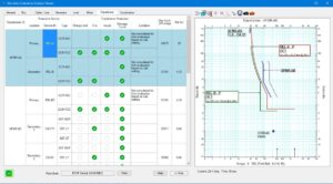
Protection Device Coordination Analysis
The objective of a protection scheme in a power system is to minimize hazards to personnel and equipment while allowing the least disruption of power service.
Coordination studies are required to select or verify the clearing characteristics of devices such as fuses, circuit breakers, and relays used in the protection scheme.
These studies are also needed to determine the protective device settings that will provide selective fault isolation.
In a properly coordinated system, a fault results in interruption of only the minimum amount of equipment necessary to isolate the faulted portion of the system.
Short-circuit results establish minimum and maximum current levels at which coordination must be achieved and which aid in setting or selecting the devices for adequate protection.
Relevant Contents
https://powerworldacademy.com/design-and-analyses-concepts-of-power-systems/