Introduction To Maintenance Mode
The Arc Flash Mitigation with Maintenance Mode provides a method to reduce clearing time of arc flash energy. A circuit breaker equipped with Maintenance Mode can improve safety by providing a simple and reliable method to reduce fault clearing time. Maintenance Mode uses a separate analog trip circuit that provides faster interruption times than the standard (digital) “instantaneous” protection. Work locations downstream of a circuit breaker with a Maintenance Mode unit can have a significantly lower incident energy level.
Benefits of Molded Case Circuit Breaker with Maintenance Mode
- Increased worker safety, when enabled, Maintenance Mode provides an accelerated instantaneous trip to reduce arc flash
- The operator can pre-select from five levels of protection to facilitate the maximum arc-flash reduction while avoiding nuisance tripping during planned startup and maintenance operations without disturbing the normal operational trip unit settings.
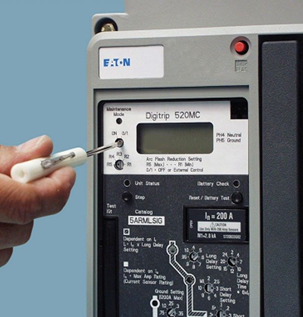
- Once the setting for Maintenance Mode has been properly chosen, Maintenance Mode is enabled by a simple lockable switch that can be incorporated into a lockout/tagout (LOTO) procedure.
- The lockable switch is mounted on the front door, or remotely, up to 9.78 ft (3m) away from the breaker, eliminating the need to open the door to enable it (no special PPE required).
- Maintenance Mode is designed to be used only during the time that a worker is exposed to the flash hazard. Maintenance Mode is not activated or armed continuously. This feature improves overcurrent coordination when compared to a permanently installed instantaneous trip element on the same circuit breaker
- Reduction in incident energy levels may allow reduced levels of PPE to be used, offering an improvement to worker comfort and mobility.
- When properly applied, the hazard risk category frequently can be lowered one or two categories, permitting less PPE.
How is Maintenance Mode used to reduce incident energy?
When Maintenance Mode is enabled and fault current is detected, the clearing time of the associated circuit breaker is reduced.
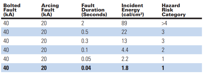
The table below shows how incident energy varies with fault duration times where the bolted fault level is 40 kA:
How is the pickup setting of Maintenance Mode chosen?
The pickup settings must be chosen by a person who is qualified in power system analysis. The initial setup of each Maintenance Mode System will require power system analysis to determine the fault currents that flow through the circuit breaker associated with the Maintenance Mode unit. Maintenance Mode has five pickup settings that are based on multiples of the per unit secondary current monitored by the trip unit of its associated circuit breaker (2.5X, 4X, 6X, 8X or 10X rating plug).
The pickup setting is chosen using the following steps:
- Calculate the arcing fault current that could flow through the circuit breaker associated with the Maintenance Mode System. The table shows that arcing fault current is much lower than that of the bolted fault current. Formulas from IEEE STD 1584TM-2002 are used to calculate the arcing current.
- Determine the total transient load current that can flow to loads fed by the circuit breaker equipped with the Maintenance Mode System. These can include motor inrush and transformer inrush.
Choose a pickup setting for the Maintenance Mode System that is:
- Below 75% of calculated arcing current.
- Above the total transient load current.
Myths about Maintenance Mode System unit
Myth 1: All it does is turn the instantaneous setting down to a lower value.
FALSE: Unlike other products, the Maintenance Mode System involves a separate circuit that acts faster than the standard “instantaneous” protection.
The Maintenance Mode System is an analog circuit that provides faster interruption times versus the digital “instantaneous” protection (~20 ms faster).
Faster interruptions = less fault current let through = less arc flash energy
Myth 2: Nuisance trips occur because of noise.
FALSE: Noise does not affect protection as explained for activation methods that follow:
Local at the trip unit—The Maintenance Mode System circuit has passed all the tests that a normal trip unit needs to pass for noise immunity: RF, Surge, Burst. This is as robust as any normal molded case circuit breaker.
External switch—The trip unit circuit is in Off/Remote Enable mode. An external switch can then be mounted on the gear and wired to the breaker to enable or disable the mode. This has been tested up to 9.78 ft (3m) away from the switch to the breaker. It has passed all the “noise” tests at that maximum length. For added assurance, WEG recommends that the switch be mounted reasonably close to the breaker.