Design and analyses concepts of power systems help electrical engineers to study steady state and dynamic behavior in electrical system. Electrical power systems are the most complex man-made nonlinear systems on earth. Also these are highly dynamic in nature.
Consider that the circuit breakers are closing and opening, the generation is varying according to load demand, and the power systems are subjected to disturbances of atmospheric origin and switching operations. The energy state of the power systems is constantly changing and the energy is being redistributed into electromagnetic and mechanical systems.
Yet, we study electrical power systems in the steady state; though, it may last for a short duration. The transition from one steady state to another does not take place instantaneously and transition to each steady state should be acceptable and stable.
The study of power systems in steady-state amounts to taking a still picture of continuously varying natural phenomena like sea waves. The study of transients that lead from one steady state to another requires transient analysis. The four volumes of this series present steady-state analysis of power systems for the material covered in these volumes.
However, the transient analysis is presented as required. There cannot be a water tight compartment between the steady state and the transient state—one may lead to another. For example, short circuits in AC systems are decaying transients and subject the power system to severe stresses and stability problems, yet empirical calculations as per standards are applied for their calculations.
1. Static and Dynamic Systems
A time-invariant resistor connected to a sinusoidal source takes a current depending on the value of the resistor and the applied voltage. The output, the voltage across the resistor, is solely dependent on the input at that instant. Such a system is memoryless and is a static system. The energy is dissipated as heat.
On the other hand, a capacitor or an inductor is not memoryless. Below figure shows a resistor and a capacitor connected to a voltage source.
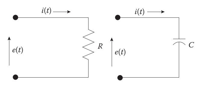
For the resistor at, any time: e(t) = R × i(t)
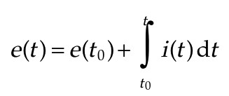
For the capacitor,
2. Static Variables
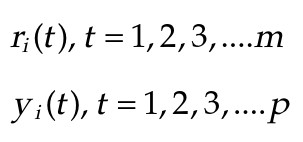
When we are interested in terminal behavior of a system, i.e., for certain inputs, there are certain outputs, the system can be represented by a simple box. There can be multiple inputs and outputs as shown in below figure:

The mathematical model specifies the relations between the inputs and outputs:
3. Linear and Nonlinear System
It is pertinent to define mathematically linearity and nonlinearity, static, and dynamic systems.
Linearity implies two conditions:
- Homogeneity
- Superimposition
This chapter has the following contents in the book:
| Title | Short-Circuits in AC and DC Systems (ANSI/IEEE and IEC Standards – Volume 1) |
| Authors | J. C. Das (Power System Studies, Inc., Snellville, Georgia, USA) |
| Size / Pages | 1.132 MB / 32 Pages |
One Response
Thanks very much for your efforts.