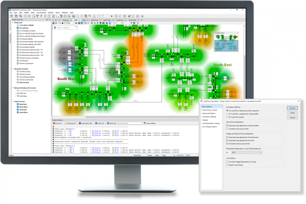
This article shows the step by step process on how to run DIgSILENT Load Flow Analysis. This will help engineers to practice on how to run load flow analysis on DIgSILENT Power Factory Software.
Sample Network Model
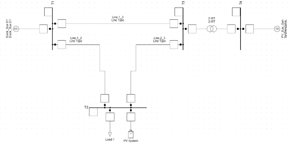
You can setup a simple network model and perform a load-flow simulation for the following Network Model:
Creating a New Project
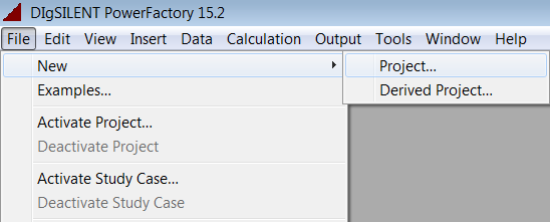
In order to setup a network model first you need to create a New Project. New Project Can be created as: File>>New>Project as below:
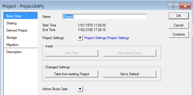
Provide a suitable name for the project.
Set-up Network Model
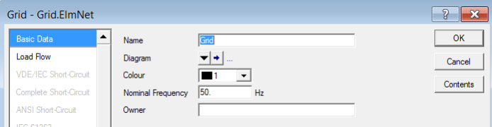
Grid
This window is the drawing-broad where you can create your network model.
Placing the Power System Components
First, place all the components in the DIgSILENT PF drawing-board and construct the network model graphically.
Hints:
Placing Busbars/ Terminals:
- First click on the busbar element in the drawing toolbar, and then place the element by clicking on the area where you want to place it in the drawing-board.
Placing the Transmission Lines and Transformer elements:
- You can connect a Transmission Line or a Transformer element by first selecting the object from the drawing toolbar and then left click on terminals that you wish to connect the element.
- The method above connects an orthogonal line directly between the two terminals. To create a more complicated route, you can left click at various ’way-points’ in the drawing-board after selecting the first terminal.
Setting-up the Parameters for Power System Devices/ Objects
The next step is to set-up the parameters for the various devices in the network model. You need to double-click on each device to set the parameters. The “Basic Data” Tab allows you to set-up the “Type”. Each component must have “Type” and type specifies the general parameters of components.
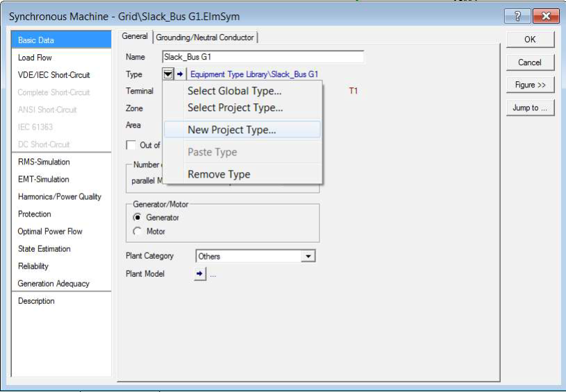
Setting the Parameters for Synchronous Generators
Double-click on the Synchronous Generator Element to open the parameter page. When you navigated to the “Basic Data” Tab, click on Type, and then click on “New Project Type”.
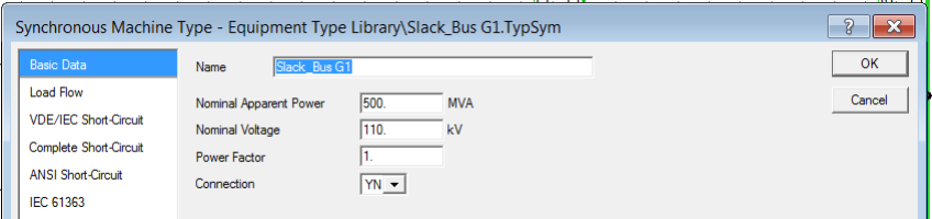
Specify the MVA capacity of the generator and voltage at the generator terminals in the “Basic Data” Tab. You don’t need to change any data in the “Load Flow” Tab unless the generator reactance/resistance data is specified in the datasheet.
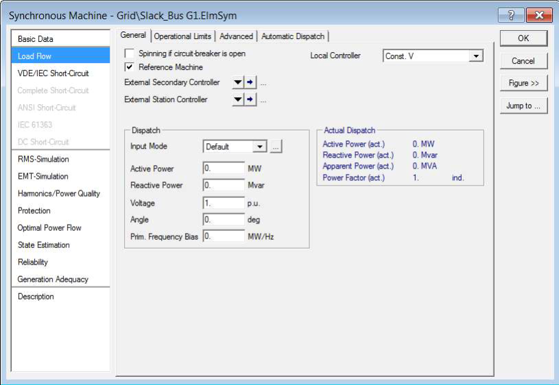
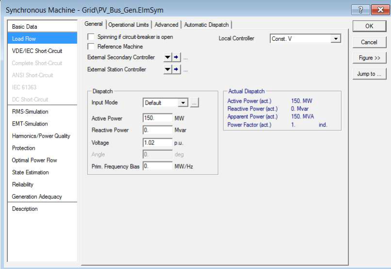
Once the parameters for the generator type are specified, the next step is to specify the operating details for the synchronous generator. Now navigate to the synchronous generator (Not Type!) “Load Flow” Tab.
For the Slack Bus Generator (Bus 1) Specify the Following:
For the synchronous generator (Bus 4) at the PV bus, specify the following. Make sure you specify the type for the Synchronous Generator as the PV bus.
Setting the Parameters for the Busbar
Double-click on the Busbar Element to open the parameter page. Set the nominal voltage for the busbar (It is not required to specify a Type for the busbar).
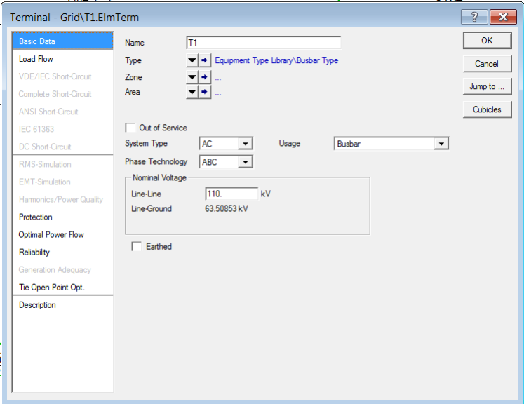
The following nominal voltages applies to the test system:
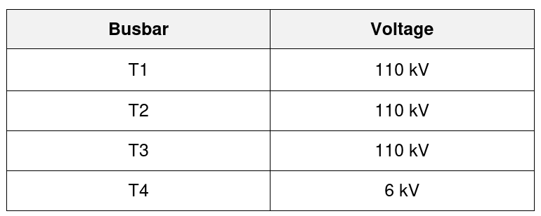
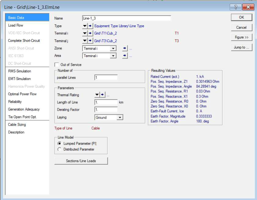
Setting the Parameters for the Transmission Lines
Double-click on the Transmission Line Element to open the parameter page. Specify the following details in the “Basic Data” Tab of the “Line Type”. Please note that you need to specify the line parameters in Ω/km, therefore if the parameters are specified in “per unit” you should convert them to Ω/km.
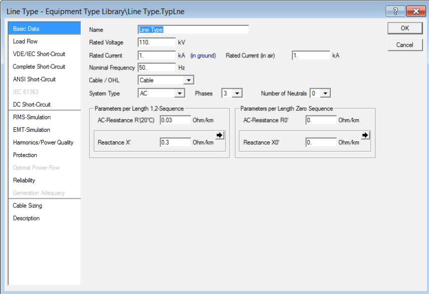
Specify the Susceptance in the Load Flow tab.
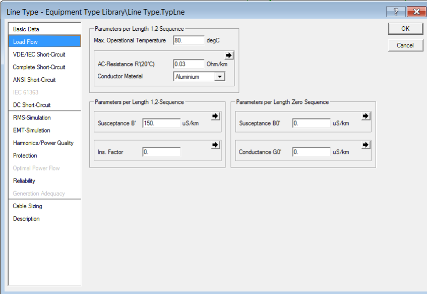
Important: If the total value of the line parameters is specified in the datasheet, assume that value as the Ω/km specification. Therefore you can specify the line length as 1 km in the “Basic Data” Tab of the line.
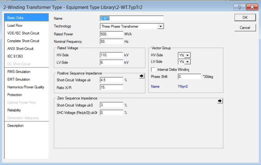
Setting the Parameters for the Transformer
Double-click on the Transformer Element to open the parameter page. Specify the following data in the “Basic Data” tab of the transformer type.
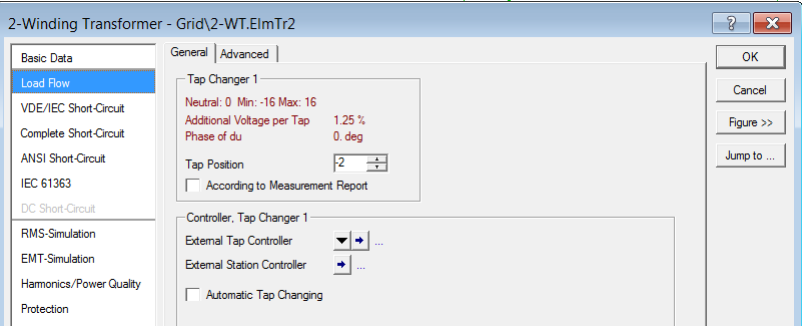
Specifying the Tap settings for the Transformer
First setup the tap changer configuration in the “Load Flow” Tab in the “Transformer Type”.
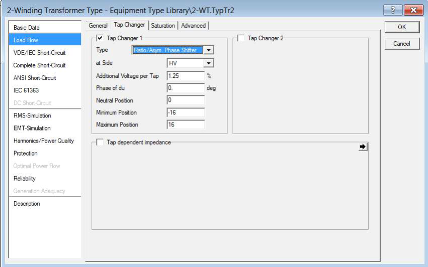
Then based on your tap requirement set the tap value at the transformer “Load Flow” Tab. If the tap setting is at the HV side and specifies as 0.975, the tap position should be -2 for the above tap specification.
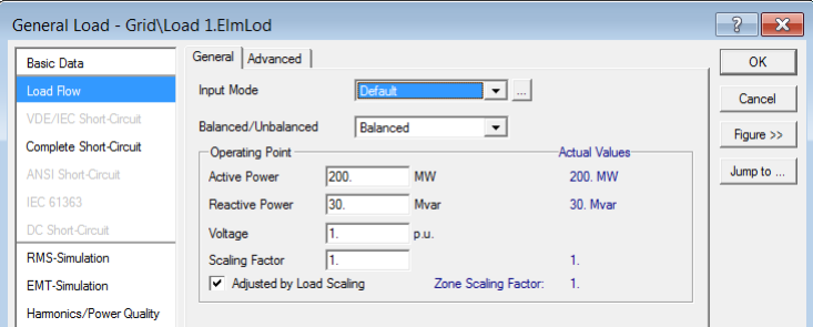
Setting the Parameters for Loads
Double-click on the Load Element to open the parameter page. You can directly enter active and reactive power in the “Load Flow” tab in the general load. It is not necessary to specify any Type for the load.
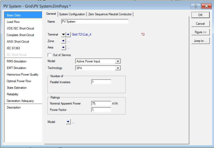
Setting the Parameters for the Solar-PV
Double-click on the solar-PV model and then navigate to the “Basic Data” Tab. Then specify the following parameters:
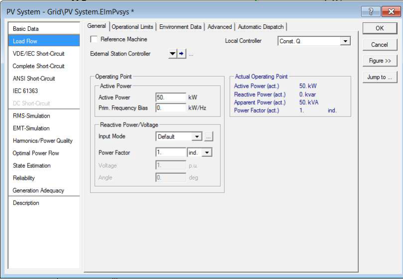
Then navigate to the “Load Flow” Tab and specify the following:
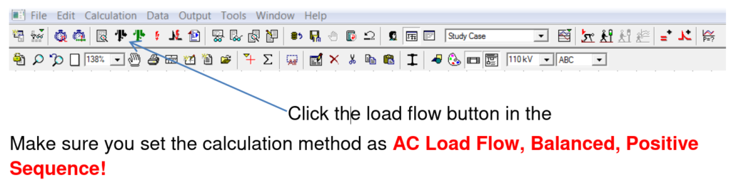
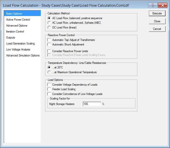
Conducting a Load-Flow Simulation
Now you have specified all the data for the test system and next step is to run the load flow by clicking on Execute button.
Load-Flow Simulation Results
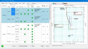
The output window will display the progress of the load flow simulation.

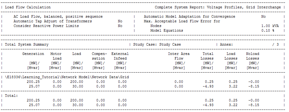
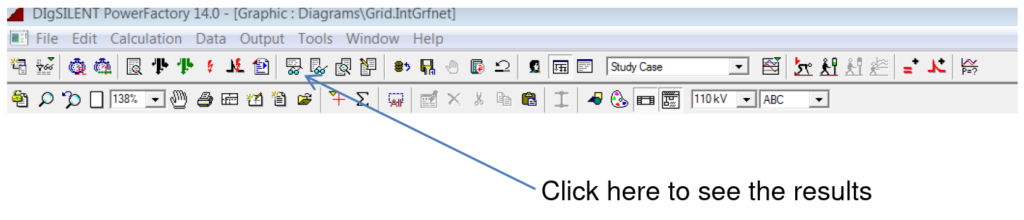
The results of the load flow can be obtained from the result boxes next to the object. However in order to obtain complete system results you need to execute the following.
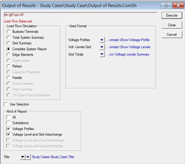
You can see the load-flow results in the output window: