Application
Directional Overcurrent Protection is useful for all network components in which the direction of flow of power is likely to change, notably in the instance of a short circuit between phases or of an earthing fault (single phase fault).
The directional protection is installed to protect two connections operated in parallel, a loop or a network component connected to two power sources
Determining The Direction For Alternating Current Flow
Current in any conductor of an electric circuit can flow from left to right or from right to left. This is commonly referred to as the direction of current flow. In dc power circuits, the polarity of the current indicates the direction of current flow. In ac power circuits, however, the polarity of the current alternates constantly. Consequently, polarity cannot be used to determine the direction of current flow.
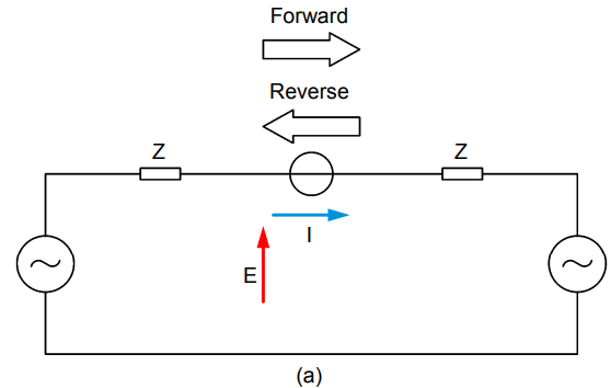
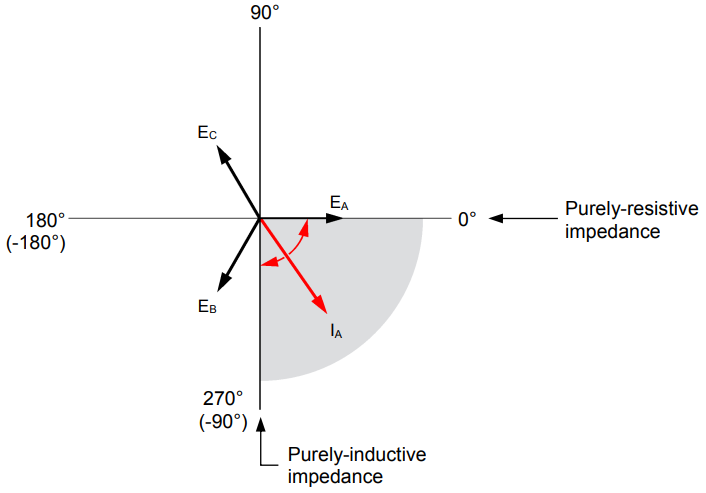
In an ac power circuit, one determines the direction of current flow from the phase shift between the voltage E and the current I at any given point of the circuit as per below figure:

When the current flows from left to right in the circuit, the absolute value of the phase shift between the voltage and current is 90° or less (Figure b), the exact value of the phase shift being dependent on the value of the circuit impedance Z. This direction is generally considered as the forward direction. On the other hand, when the current flows from right to left in the circuit, the absolute value of the phase shift between the voltage and current is 90° or more (Figure c), the exact value of the phase shift being dependent on the value of the circuit impedance Z. This direction is generally considered as the reverse direction.
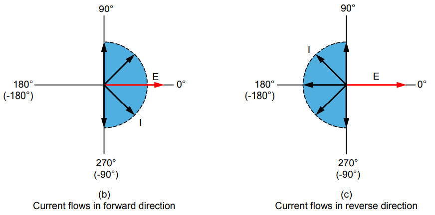
In most power networks, the impedance is of resistive-inductive nature. In this case, the expected range of phase angle values of the current is reduced to 90° for each direction of current flow as per below figure (b) and (c),
Operation of Directional Overcurrent Relay
The directional overcurrent relay is the key component to achieve directional overcurrent protection. The operation of the directional overcurrent relay (ANSI device no. 67) along with its main parameters are explained below:
- A directional overcurrent relay (ANSI device no. 67) mainly consists of an overcurrent relay plus a directional element that determines the direction of current flow.
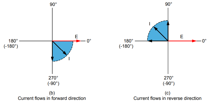
- A directional overcurrent relay measures current and voltage at a given point of the circuit as per below figure. From these measurements, the directional element is able to determine the direction of current flow.
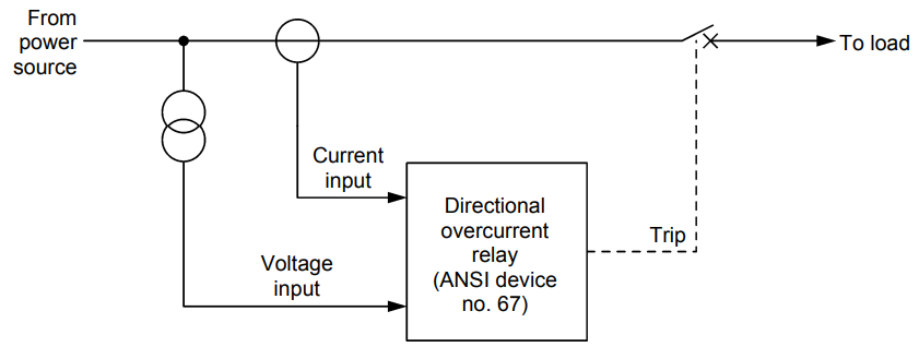
- The directional element allows the operation (tripping) of the overcurrent relay within the directional overcurrent relay only when the measured current flows in the selected direction (forward or reverse) of current flow.
- A directional overcurrent relay can monitor line current on two phases, in which case it measures two currents and two voltages. This allows detection of any phase-to-phase fault. It can also monitor line current on all three phases, in which case it measures three currents and three voltages. This allows detection of any phase-to-phase fault as well as any phase-to-ground fault.
- In electromechanical and static directional overcurrent relays, the reference voltage for phase A is generally line voltage EBC, not phase voltage EA, as one could expect. This is because voltage EBC is not affected when a ground fault occurs on phase A, thereby providing a more stable reference voltage (the same applies to phase B and phase C, i.e., line voltage ECA is used as the reference voltage for phase B and line voltage EAB is used as the reference voltage for phase C). On the other hand, modern directional overcurrent relays (digital and numerical units) generally use phase voltage EA as the reference voltage for phase A and other techniques to obtain a reference voltage that is even more stable (these techniques are beyond the scope of this manual). However, note that the settings in certain modern directional overcurrent relays replicate the settings found in electromechanical and static directional overcurrent relays even if a phase voltage (e.g., voltage EA for phase A) is used as the reference voltage instead of a phase-to-phase voltage (e.g., voltage EBC for phase A).
- The reference voltage may be rotated to properly align the forward and reverse direction zones of the directional overcurrent relay. This rotation angle is referred to as the characteristic angle. Below figure shows the forward and reverse direction zones for two values of characteristic angle when line voltage EBC is used as the reference voltage.
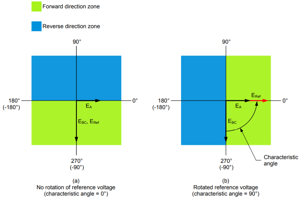
zones of the directional overcurrent relay.
Main Settings of Directional Overcurrent Relay
- Direction of current flow (forward or reverse)
- Current threshold, also referred to as the current setting. This is the minimum current for which the directional overcurrent relay may trip.
- Time delay, also referred to as the time setting or the operate delay. This is the operating time of the relay when a definite-time overcurrent relay (ANSI device no. 51DT) is used in the directional overcurrent relay. When an inverse definite minimum time overcurrent relay (ANSI device no. 51I) is used, the operating time is calculated according to the chosen time-current characteristic.
- Characteristic angle. Angle by which the reference voltage is rotated to allow proper operation of the directional overcurrent relay. This angle is generally set to 45°. This is explained in the following section.
Typical Value (45°) of Characteristic Angle For Directional Relays
The range of phase angle values of current expected for faults on phase A includes the ranges of phase angle values for a phase-to-ground fault, a phase-to-phase fault between phase A and phase B, and a phase-to-phase fault between phase A and phase C. These three cases are treated separately below to ease understanding. The circuit impedance considered is of resistive-inductive nature, as this is representative of actual circuit impedances.
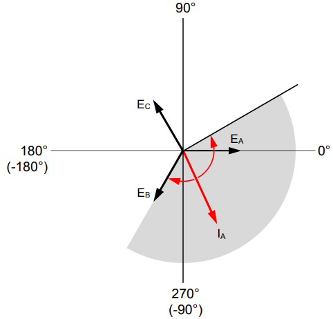
When a phase-to-ground fault occurs on phase A, the range of phase angle values of current IA that is expected is as per below figure:
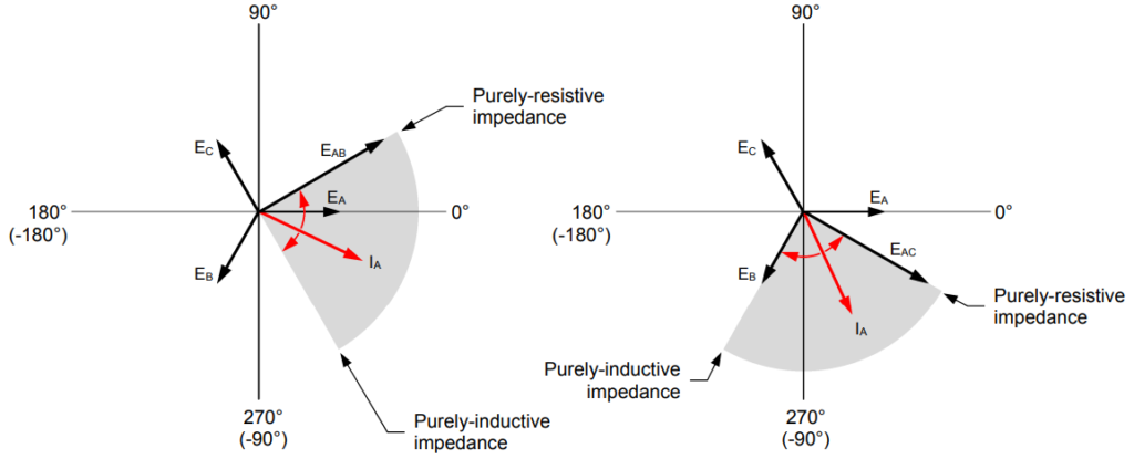
The ranges of phase angle values of current IA expected for phase-to-phase faults between phase A and phase B and between phase A and phase C are as per below figure:
The superposition of the ranges of phase angle values of current IA involved in Figure-A and Figure-B is presented in Figure-C below. The total range covers 150°. Similarly, the total range of phase angle values of the current is also 150° for faults on phase B or phase C.
Setting the characteristic angle to 45° properly aligns the forward and reverse direction zones of the directional overcurrent relay with the vectors of fault current expected for phase A, as illustrated in Figure-D. Notice that the forward direction zone encloses every expected vector of fault current for phase A with a safety margin of 15° on each side of the expected range of phase angle values of current. This ensures optimal operation of the directional overcurrent relay.
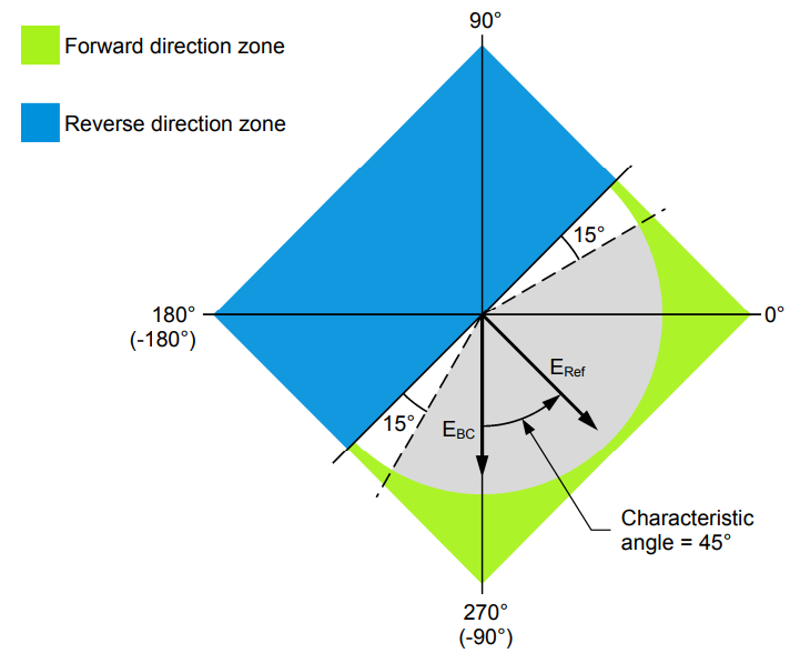
expected for the fault currents


2 Responses
An interesting approach to the analysis.
The “definitive” analysis (i.e. hard to follow but worth the effort) techniques for directional protection was published by Sonneman in a paper for AIEE Transactions back in 1950. You can find it here: https://rhconsult.tiny.us/2as8v9me
Hi Rod, thanks for sharing useful information.