Introduction
The basic function of a generator excitation control system is to provide a variable DC current to the synchronous generator field winding.
By varying the DC voltage, and thereby the field current, the generator terminal voltage and reactive power output can be regulated.
Excitation control is useful to maintain the desired operating condition and to enhance power system stability.
The protection function ensures that the capability limits of the synchronous machine, excitation system and other equipment do not exceed.
Below figures represents the excitation control system in classical feedback control form:
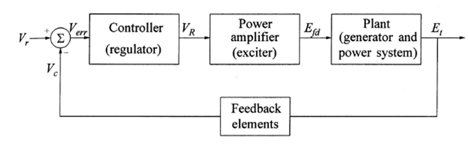
Exciter Elements and Functional Block Diagram

- Exciter: Provides DC power to the synchronous machine field winding. Normal exciter rating varies from 2.0 to 3.5 kW/MVA generator rating, e.g. for a 600 MVA synchronous generator the excitation system should provide 1.2 to 2.1 MW
- Regulator: Processes and amplifies input control signals appropriate for control of the exciter. This includes both regulating and excitation system stabilizing functions
- Terminal Voltage Transducer and Load Compensator: Senses the generator terminal voltage, rectifies and filters it to DC quantity, and compares it with a reference which represents the desired terminal voltage. In addition, load (line-drop or reactive) compensation may be provided, if it is desired to hold constant voltage at some point electrically remote from the generator terminal (e.g. to compensate the drop of step-up transformer connected between generator and main bus)
- Power System Stabilizer: Provides an additional input signal to the regulator to damp power system oscillations. Some commonly used input signals are rotor speed deviation, accelerating power and frequency deviation
- Limiters and Protective Circuits: These include a wide array of control and protective functions which ensure that the capability limits of the exciters and synchronous generators do not exceed.
- Some of the most commonly used functions are the field-current limiter, maximum excitation limiter, terminal voltage limiter, volts-per-Hertz regulator and protection and under-excitation limiters.
- These are normally distinct circuits and their output signals applies to the excitation system at various locations as a summing input. For convenience, they have been grouped and shown in this figure as a single block.
- The Over-Excitation Limiter (OEL) offers protection from overheating due to high field current levels while allowing maximum field forcing capability (power system stability purposes). The Under-Excitation Limiter (UEL) acts to boost excitation in order to avoid under-excited operation.
Types of Excitation Control System
- DC Excitation System
- AC Excitation System
- Static Excitation System
DC Excitation System
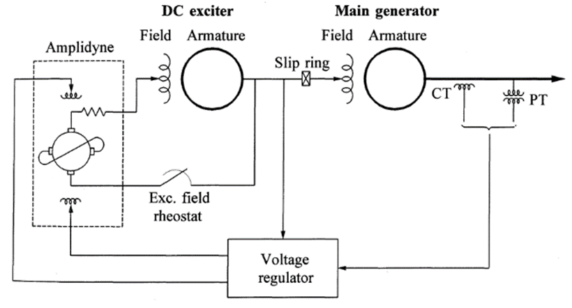
- The figure shows the typical DC excitation system with an amplidyne voltage regulator. It uses DC generators as source of excitation power and provide DC current to the rotor of the synchronous machine through slip rings. Exciter field is controller by an amplidyne
- They are either self-excited or separately excited. When separately excited, a pilot exciter comprising a permanent magnet generator supplies the exciter current.
- Voltage regulator for such systems range from the early stages of rheostatic type to the later systems utilizing magnetic and rotating amplifiers
- DC excitation systems are gradually disappearing and replaced by AC or Static type systems. In some cases, the voltage regulators alone have been replaced by modern solid-state electronic regulators
AC Excitation System
- AC excitation system normally utilizes AC machines/alternators as sources of the main generator excitation.
- Usually, exciter is on the same shaft as the turbine generator.
- AC output of the exciter is rectified by either controlled or non-controlled rectifiers to produce direct current needed for the generator field
- These rectifiers are Stationary (controlled/non-controlled) and Rotating
- Early AC excitation systems used a combination of magnetic and rotating amplifiers as regulators. Most of new systems use electronic amplifier regulators.
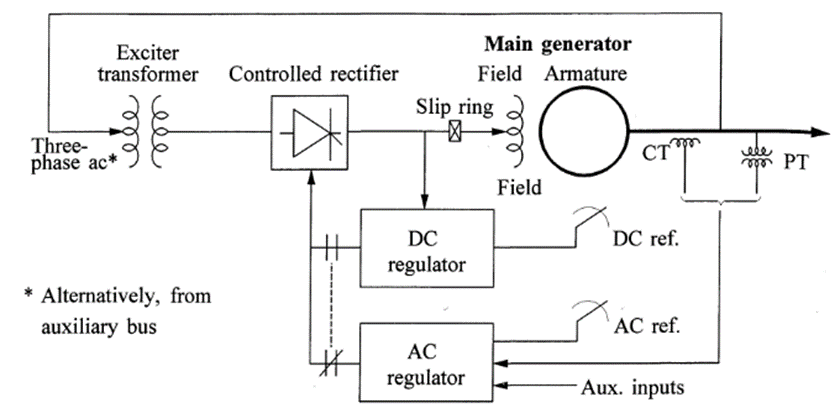
a) AC Excitation System – Stationary Rectifiers
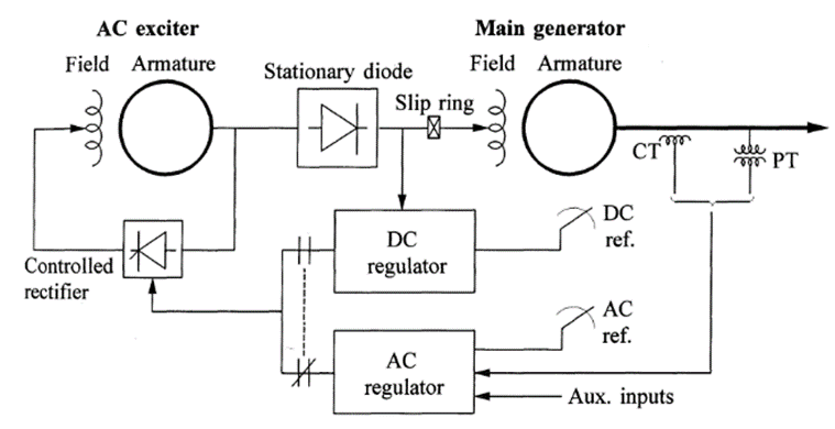
- With stationary rectifiers, DC output is fed to the field winding of the main generator through slip rings
- With non-controlled rectifiers, the regulator controls the field of the AC exciter which in turn controls the exciter output voltage
- The exciter exciters itself with its field power derived through thyristor rectifiers. The voltage regulator derives its power from the exciter output voltage
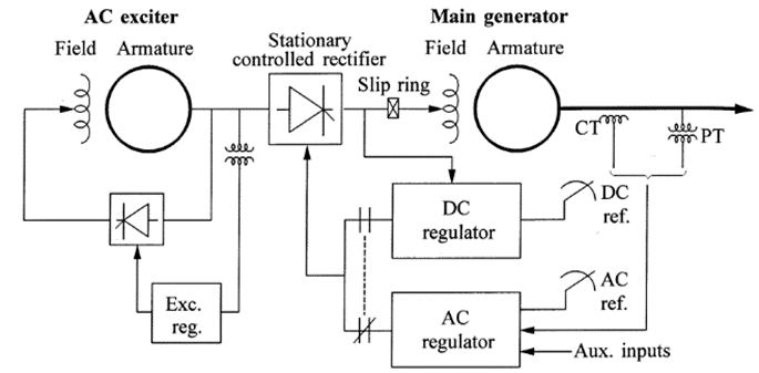
- With controlled rectifiers, the regulator directly controls the DC output voltage of the exciter
- The voltage regulator controls the firing of the thyristors
- The self-excited exciter alternator uses an independent static voltage regulator to maintain its output voltage
- Since, thyristors directly control the exciter output, this system provides high initial response (small response time)
b) AC Excitation System – Rotating Rectifiers
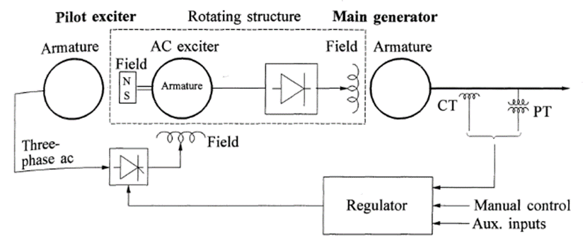
- Rotating rectifiers do not required the slip rings and brushes (hence brushless). The DC output is directly fed to the main generator field.
- The armature of AC exciter and the diode rectifiers rotate with the main generator field
- A small AC pilot exciter, with a permanent magnet rotor (NS field) rotates with the exciter armature and the diode rectifiers
- The rectified output of the pilot exciter stator energizes the stationary field of the AC exciter
- The voltage regulator controls the AC exciter field, which in turn controls the field of the main generator
- Brushless excitation systems do not allow the direct measurement of generator field current or voltage. Manual control of main generator voltage is provided by an adjustable DC input setting to the thyristor gating circuits
Static Excitation System
- All components in these systems are static or stationary.
- Static rectifiers supply the excitation current directly to the field of the main synchronous generator through slip rings.
- The supply of power to the rectifiers is from the main generator (or station auxiliary bus) through a transformer step down the voltage to an appropriate level
- The maximum exciter output voltage (ceiling voltage) is dependent on the input AC voltage.
- Hence, during system-fault conditions causing depressed generator terminal voltage, the available exciter ceiling voltage reduces and hence this requires high field-forcing capability
- Inexpensive and easily maintainable