Why Stator Ground Fault Protection is required?
Generator stator ground fault protection is one of the indispensable schemes for protecting a generator stator winding. Dedicated stator ground fault protection is required for high-impedance-grounded machines.
Because of stator winding construction, an insulation failure is more likely to result in a winding-to- ground fault than in a phase-to-phase fault.
Other failures, such as a broken conductor or turn-to-turn fault, may not be detected until the fault develops into a winding-to-ground fault.
Concepts of Stator Ground Fault Protection
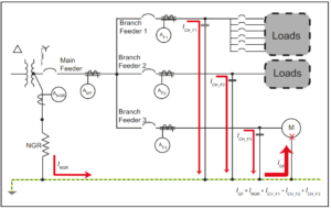
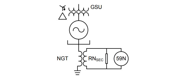
The stator ground fault protection for a high-impedance grounded generator is typically provided with neutral overvoltage (59G), which covers about 95% of the winding measured from the output terminals as shown below:
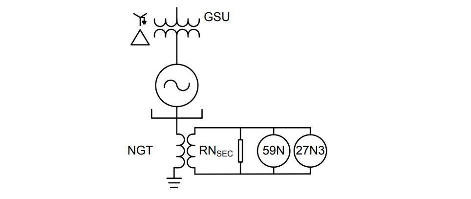
In order to provide 100% coverage for ground faults, third (3rd) harmonic voltage schemes can be used in high impedance grounded generators to complement the 59N element as shown below:
Third-Harmonic Neutral Undervoltage (27N3) Protection
Harmonic voltages are generated during the normal operation of generators. This is mainly due to physical limitations in the design of the machines. The triplen-harmonics (e.g., third, ninth, and fifteenth) are each produced in equal magnitude and phase on all three phases.
The result is that the triplen harmonic voltages are zero-sequence voltages, with the third-harmonic voltage being the largest harmonic.
Field Measurement of Third Harmonic Voltages
Field measurements of third harmonic voltages during various loading conditions are required in order to set this function.
Below table gives the typical measured third harmonic voltages (based on primary of the grounding transformer) for generator:
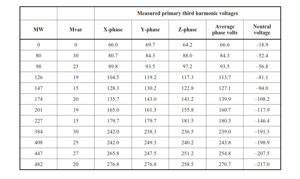
In above table, the terminal end voltage is shown as positive voltage, whereas the neutral end voltage is shown as negative voltage. The voltage may be considered evenly distributed along the length of the generator winding. Normally, the third harmonic voltage will vary with MW and MVAr.
Analysis of Field Measurement of Third Harmonic Voltages
Measured primary harmonic voltages at the terminal end and neutral end, are plotted below:
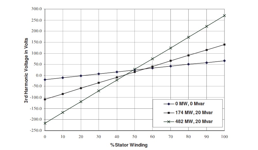
Note that because the measured third harmonic voltage is different for each generator load, the slope of each respective line is different. Because the line slopes are different, the point that the line crosses the X- axis changes for different load conditions.
The third harmonic relay scheme measures the magnitude of the generator neutral third harmonic voltage, and operates when that voltage magnitude is reduced below the trip point. The relay determines the absence of a third harmonic voltage as an abnormal condition.
Therefore, either the relay setting is set below the minimum expected generator neutral third harmonic voltage magnitude or there needs to be some type of supervisory control over the relay operation.
Normally, the generator terminal voltage is used to supervise the relay output. In some cases generator forward power also supervises the relay tripping. However this will leave the generator unprotected on start-up.
Settings of 27TH/27N3 Relay
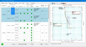
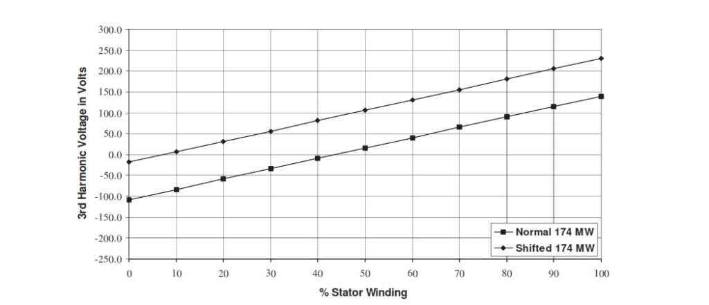
Assuming a 27N3 ( can be referred as 27TH as well) relay pickup of 18 V, the percentage of winding covered for a 174 MW loading is around 7% from the neutral end as shown in below figure:
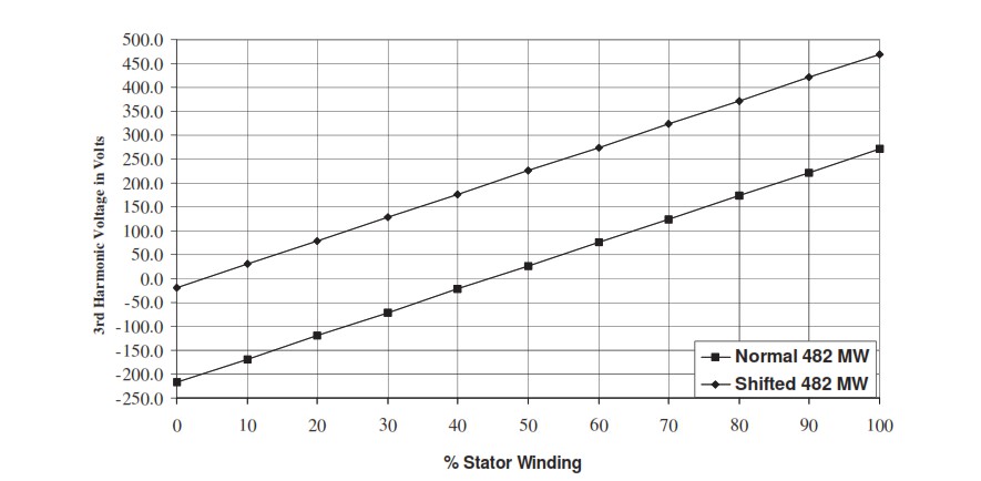
Assuming the same 18 V relay pickup, and a new load of 482 MW, the fault would have to be closer to the generator neutral (than for the 174 MW condition) in order for the relay to detect the fault.
This is due to the higher slope of the 482 MW line. For the 482 MW line, the fault would have to be within 3.7% of the neutral to be detected as shown in below figure:
Determining Percentage Coverage of Third Harmonic Relay
To obtain security against relay mis-operation while providing continuous coverage, a ratio of the minimum normal generator neutral third harmonic voltage to relay pickup of 2:1 would be preferred.
In this example, with the no-load generator neutral third harmonic voltage at -18.9 V (as per measured primary third harmonic neutral voltage table), the preferred relay setting would be around 9 V to 10 V.
The third harmonic undervoltage relay is used in conjunction with other relays to obtain the total ground fault protection of the generator stator.
The other relays cover from the generator terminals to the point of minimum sensitivity as previously determined, with some overlap of the protective zones.
Relay Sensitivity
A 59G setting of 5 V will be used to demonstrate this principle. A ground fault at the generator’s terminal results in the maximum voltage across the grounding transformer’s primary.
The 59G relay will measure that primary voltage, reflected to the secondary by the transformer ratio.
The sensitivity of the relay (percent coverage) is determined by the relay pickup. The maximum secondary voltage the relay will measure in this installation is:
= ( 20,000 V ) / (sqrt(3) x 60 ) = 192.45 V
where, 20,000 V is Generator Voltage, 60 is NGT voltage ratio ( considering NGT voltage ratio as 14400 / 240 V )
The grounding transformer secondary non-fault voltage is normally zero. Since the relay operates when the secondary voltage rises above its pickup (5 V in this case), the relay will operate for all faults except those within 2.6% ( 5 V / 192.45 V = 0.026 or 2.6 % ) of the neutral end of the generator.
The time setting for the 59G relay is selected to provide coordination with other system protective devices. A time delay setting of 5 seconds is suggested for 59G relay.
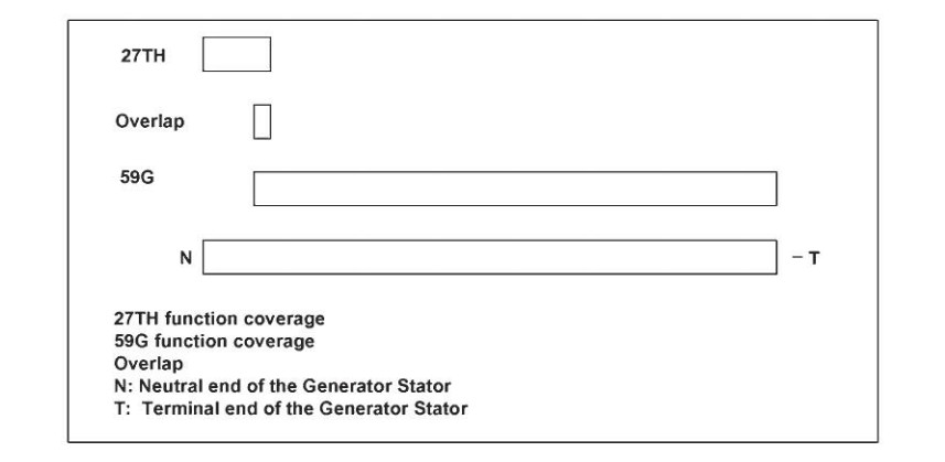
The relay will cover 100 – 2.6 = 97.4% of the generator. Therefore, there is complete coverage, since the 27TH function will cover between 0% to 3.7% and the 59G relay will cover between 2.6% to 100% of the
winding.
Below figure illustrates the overlapping of the third harmonic relay function (27TH) and the normal stator ground protection (59G). An independent 50/51G relay connected at the generator neutral provides a redundant trip for stator ground faults.
Summary of Settings
59G element: Pickup = 5 V and Time Delay = 5 sec
27TH/27N3 element: Pickup = 18 V (Primary) or 0.3 V secondary [ ( 14400 / 240 ) x 18 ]
18 V pickup is close to the minimum measured third harmonic voltage during no load. Hence, 27TH function should be supervised by a forward power element to prevent tripping during start-up. Alternatively, the pickup of the 27TH function could be dropped to 0.15 V (if possible).