Harmonic analysis methods help engineers to calculate system harmonic levels resulting from harmonic sources on the system. This also requires a knowledge of the harmonic source characteristics and a representation of the system frequency response characteristics.
Below sections cover the aspects of harmonic levels and harmonic frequency response of harmonic analysis:
Harmonic Current Calculations
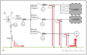
Most harmonic sources represent as ideal current sources for analysis purposes. That is, for analysis at each harmonic frequency, the nonlinear device represents a current source as indicated in below figure:
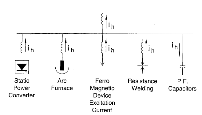
For most nonlinear devices, the representation is quite accurate up to harmonic voltage distortion levels of at least 10%.
The specific characteristics for different types of nonlinear devices fall into three general categories:
1) Power electronic type devices (converters, etc.)
2) Arcing type devices (arc furnaces, fluorescent lights)
3) Ferromagnetic devices (transformers)
For power electronic type devices, the harmonic generating characteristics can often be determined analytically. For arcing devices and transformers, it is usually necessary to use typical characteristics, unless better information is available.
System Frequency Response Calculations
Once the harmonic source characteristics are determined, the response of the system to these sources should be calculated. Important elements of the model used to perform these calculations include the following:
1) System short-circuit equivalent impedance
2) Capacitor banks
3) Characteristics of lines and cables on the system
4) Load characteristics
The system analysis can be performed using relatively simple hand calculations for some industrial circuits and simple distribution systems. However, most systems require some type of computer simulation program that can represent the system at multiple frequencies for analysis.
Simple Calculations
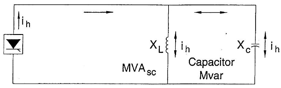
This circuit is adequate for analyzing many industrial circuits and some distribution circuits where capacitors are applied at the substation.
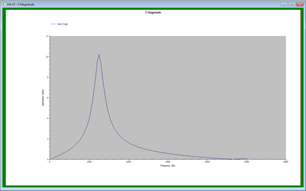
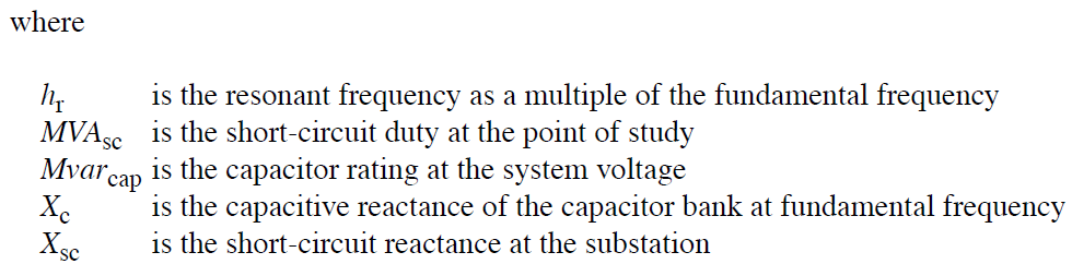
The most important calculation for this circuit is the resonant frequency as below:
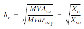
If the calculated resonance is near one of the characteristic harmonics of the source, the potential for problems needs further evaluation.
The next step is to calculate the actual system impedance at the characteristic harmonics of the source:
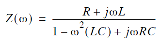
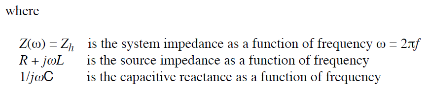
Once Zh is obtained at each characteristic harmonic, the voltage magnitude can be calculated at each harmonic as follows:
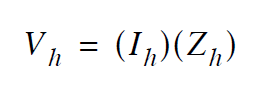
where, Ih = the source current at each characteristics harmonic