This article covers all about the introduction to impedance method for calculating voltage drop during motor start, sample hand calculation and its comparison with ETAP software.
Introduction To Impedance Method
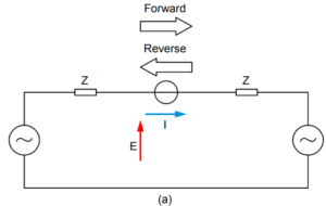
Impedance method for calculating voltage drop during motor start involves the reduction of the system to a simple voltage divider network. In this method, voltage at any point (bus) in a circuit is found by taking known voltage (source bus) times the ratio of impedance to the point in question over total circuit impedance.
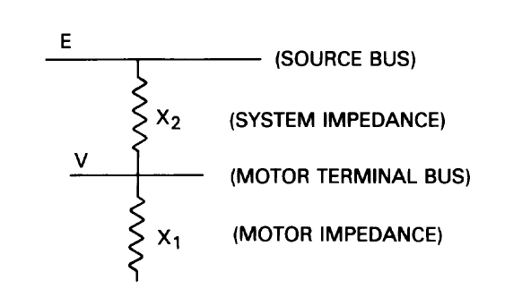
For above circuit, using voltage divider theory, we can write the motor terminal bus voltage as below:

or more generally,

Above expression for V also analyze the effect of adding a large capacitor bank at the motor bus. The addition of negative vars causes X1 or Z1 to become larger in both numerator and denominator. Hence, the bus voltage V increases and approaches 1.0 per unit as the limiting improvement.
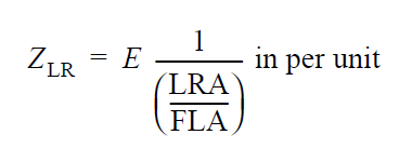
Locked-rotor impedance for three-phase motor is given by:
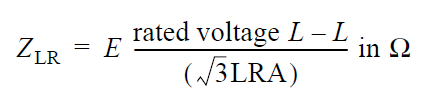
This value in per unit is equal to the inverse of the inrush multiplier on the motor rated kVA base:
A starting motor is accurately represented as a constant impedance course. Hence, the impedance method is a very convenient and acceptable means of calculating system bus voltages during motor starting.
Validity of the impedance method can be seen and is usually used for working hand calculations. Where other than simple radial systems are involved, the digital computer greatly aids in obtaining necessary network reduction.
To obtain results with reasonable accuracy, however, various system impedance elements must be represented as complex quantities rather than as simple reactances.
Sample Calculation For Calculating Voltage Drop During Motor Start
Step-1: Enter Source / Grid and Motor Input Data
Step-2: Calculate Source Impedance at Source MVA and Convert to Common 100 MVA Base (Z2)
Step-3: Calculate Motor Impedance in Locked-Rotor Condition and Convert to Common 100 MVA Base (Z1)
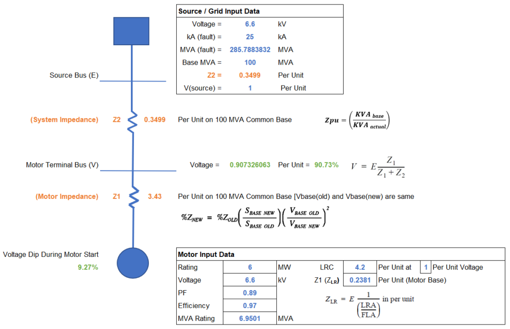
Step-4: Calculate Motor Terminal Bus Voltage and Voltage Dip During Motor Start
Motor Terminal Bus Voltage (V) = E [ Z1 / ( Z1 + Z2 ) ] = 1 [ 3.43 / ( 3.43 + 0.35 ) ] = 0.9074 Per Unit OR 90.74%
Voltage Dip During Motor Start = 100 % – 90.74 % = 9.26 %
Simulation and Comparison With ETAP Software
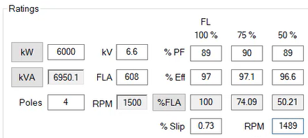
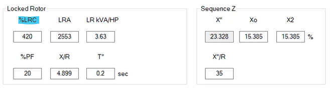
Motor Input Data
ETAP Plot Result For Motor Starting Voltage Dip With 25 KA Source Fault Current

Conclusion
It can be concluded that the voltage (V) at motor terminal bus derived (Figure-(1)) using Impedance Method or Voltage Divider Method is 90.73 % which is closely matching with the value of 90.8 % as shown in Figure-(2).
Relevant Contents
- https://powerworldacademy.com/per-unit-method/
- https://powerworldacademy.com/voltage-drop-causes-and-effect-with-calculation-example/
- https://powerworldacademy.com/effect-of-voltage-variations-on-induction-motor-characteristics/
- https://www.cedengineering.com/userfiles/Introduction%20to%20Motor%20Starting%20Analysis-R1.pdf