
Introduction
Power system switching transients occur each time, an abrupt circuit change occurs.
This circuit change is usually the result of a normal switching operation, such as breaker opening or closing or simply turning a light switch on or off.
Bus transfer switching operations, inception and clearing of system faults, also cause power system switching transients.
The phenomena involved in power system transients can be classified into two major categories:
- Interaction between magnetic and electrostatic energy stored in the inductance and capacitance of the circuit, respectively which is called electro-magnetic transients
- Interaction between the mechanical energy stored in rotating machines and electrical energy stored in the inductance and capacitance of the circuit which is called electro-mechanical transients
Most power system transients are oscillatory in nature and are characterized by their transient period of oscillation.
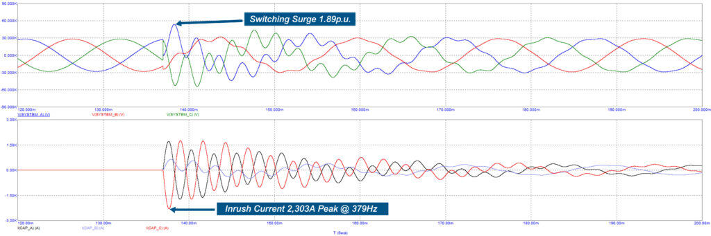
Effect of Switching Transients
Despite the fact that these transient periods are usually very short when compared with the power frequency of 50 Hz or 60 Hz, they are extremely important.
The circuit components and electrical equipment are subjected to the greatest stresses resulting from abnormal transient voltages and currents.
Over-voltages may result in flashovers or insulation breakdown, overcurrent may damage power equipment due to electromagnetic forces and excessive heat generation.
Flashovers usually cause temporary power outages due to tripping of the protective devices, but insulation breakdown usually leads to permanent equipment damage.
For this reason, a clear understanding of the circuit during transient periods is essential in the formulation of steps required to minimize and prevent the damaging effects of switching transients.
Circuit Elements in Power System Switching Transients
All circuit elements, whether in utility systems, industrial plants, or commercial buildings, possess resistance, R, inductance, L, and capacitance, C.
Resistor
Ohm’s law defines the voltage across a time-invariant linear resistor as the product of the current flowing through the resistor and its ohmic value. That is:
Inductor
The other two elements, L and C, are characterized by their ability to store energy. The term “inductance” refers to the property of an element to store electromagnetic energy in the magnetic field.
This energy storage is accomplished by establishing a magnetic flux within the ferromagnetic material.
For a linear time-invariant inductor, the magnetic flux is defined as the product of the inductance and the terminal current. Thus,
where ∅(t) is the magnetic flux in webers (Wb), L is the inductance in Henries (H), and i(t) is the time-varying current in amperes (A).
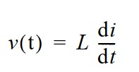
By Faraday’s law, the voltage at the terminals of the inductor is the time derivative of the flux, namely,
Combining the above Equation-(3) with Equation-(2) gives the voltage-current relation of a time- invariant linear inductor as,
Capacitor
Finally, the term “capacitance” means the property of an element that stores electrostatic energy.
In a typical capacitance element, energy storage takes place by accumulating charges between two surfaces that are separated by an insulating material.
The stored charge in a linear capacitor is related to the terminal voltage by:
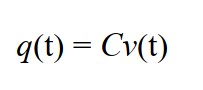
where C is the capacitance in farads (F) when the units of q and v are in coulombs (C) and volts (V), respectively.
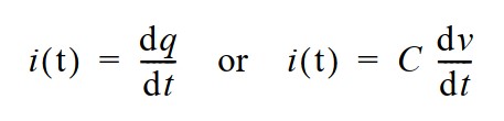
The electrical current flowing through a particular point in a circuit is the time derivative of the electrical charge. Equation-(5) can be differentiated with respect to time to yield a relationship between the terminal current and the terminal voltage. Thus,
Under steady-state conditions, the energy stored in the elements swings between the inductance and capacitance in the circuit at the power frequency.
When there is a sudden change in the circuit, such as a switching event, a redistribution of energy takes place to accommodate the new condition.
This redistribution of energy cannot occur instantaneously for the following reasons:
- The electromagnetic energy stored in an inductor is E = ( LI2 / 2 ). For a constant inductance, a change in the magnetic energy requires a change in current. But the change in current in an inductor is opposed by an emf of magnitude v(t) = L (di/dt). For the current to change instantaneously (dt=0), an infinite voltage is required. Since this is unrealizable in practice, the change in energy in an inductor requires a finite time period.
- The electrostatic energy stored in a capacitor is given by E = ( CV2 / 2 ). The current-voltage relationship is given by i(t) = C (dv/dt). For a capacitor, an instantaneous change in voltage (dt = 0) requires an infinite current, which cannot be achieved in practice. Therefore, the change in voltage in a capacitor also requires finite time.
In addition to two basic concepts mentioned above, the basic to the understanding and analysis of transients in power systems are:
- the rate of energy produced must be equal to the sum of the rate of energy dissipated and
- the rate of energy stored at all times (principle of energy conservation) are .
External Link
Below document can be referred for more detailed understanding of power system switching transients: