Overexcitation Protection For Transformers

overexcitation protection transformer

Application of Over-excitation protection

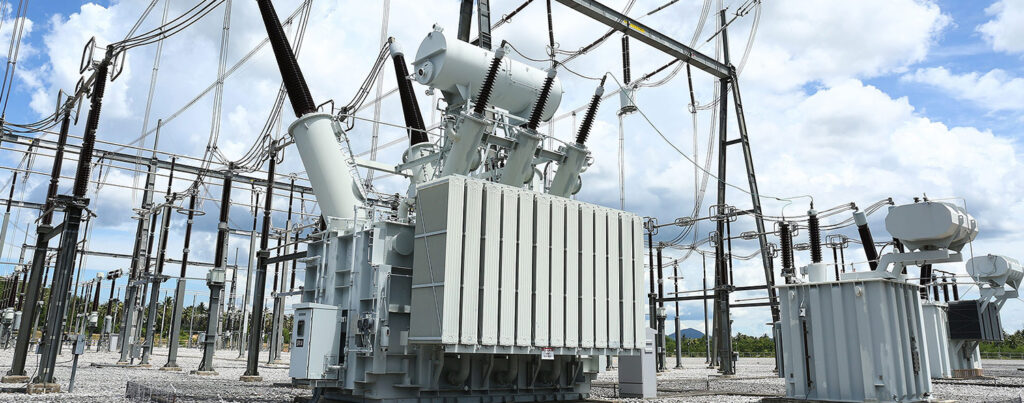
Overexcitation protection applies on direct-connected generator unit transformers.

Why to apply Over-excitation protection?

Excessive excitation current leads directly to overheating of core and unlaminated metal parts of a transformer.

Such overheating in turn causes damage to adjacent insulation and leads to ultimate failure.

IEEE Std C57.12.00-2000 requires that transformers shall be capable of operating continuously at 10% above rated secondary voltage at no load without exceeding the limiting temperature rise.

The requirement applies for any tap at rated frequency. 

Direct-connected generator transformers subjects to a wide range of frequency during the acceleration and deceleration of the turbine. 

Settings for Over-excitation protection

Under the conditions as mentioned above, the ratio of the actual generator terminal voltage to the actual frequency (V/f or V/Hz) shall not exceed 1.1 times the ratio of transformer rated voltage to the rated frequency on a sustained basis:

voltage by frequency

Generator manufacturers now recommend an overexcitation protection system as part of the generator excitation system to protect the transformer against overexcitation.

These systems may alarm for an overexcitation condition; and, if the condition persists, they may decrease the generator excitation or trip the generator and field breakers, or both.

The generator and transformer manufacturers should provide their recommendation for overexcitation protection. 

Overexcitation relays (i.e., V/Hz) may be used on transformers located either at or remote from generating stations.

They are available with a definite time delay or an inverse-time overexcitation characteristic to connect for trip or alarm. 

Below provided link helps to gain more knowledge on overexcitation protection of transformers:

https://www.microener.com/contenu/uploads/2012/08/VPH24_PRELIM-ME.pdf

Related Posts

Electrical Equipment
Chief Editor

Selection of NGR (Neutral Grounding Resistor)

Selection of NGR mainly depends on key factors such as the voltage rating, the time rating and the let-through-current rating. Voltage Rating An NGR must be rated for system line-to-neutral voltage—the voltage across the resistor when a single-phase bolted ground

Read More »
protection coordination
ETAP
Chief Editor

Protection and Coordination Analysis

This article demonstrates the high level step by step procedure to perform the protection and coordination analysis in ETAP software. Below are the steps: Select protective devices models from editor Once the single line diagram and data entry is complete

Read More »
directional protection
Protection
Chief Editor

Directional Overcurrent Protection

Application Directional Overcurrent Protection is useful for all network components in which the direction of flow of power is likely to change, notably in the instance of a short circuit between phases or of an earthing fault (single phase fault).

Read More »
Tur-Gov
Electrical Equipment
Chief Editor

Generator Turbine Governor Control

Introduction The generator turbine governor control regulates rotational speed in response to changing load conditions. The governor output signal manipulates the position of a steam inlet valve or nozzles which in turn regulates the steam flow to the turbine. Turbine-generator

Read More »
PV inverter
General
Chief Editor

Inverter Controls in AC Microgrids

Inverter controls in AC microgrid allows delivering distributed power and providing grid support services during regular operation of the grid. It also allows the powering isolated islands in case of faults/contingencies to increase the performance and reliability of electrical system.

Read More »
short circuit
General
Chief Editor

X/R Ratio in Low-Voltage Short Circuit Studies

This article discusses about the importance of X/R ratio in low voltage short circuit studies. Introduction In some short circuit studies, the X/R ratio is ignored when comparing the short circuit rating of the equipment to the available fault current

Read More »

Author Information

Comments

Leave a Reply

Your email address will not be published. Required fields are marked *