Per-Unit Method

per unit method

Fundamentally, the per-unit method (percentage method) is a calculating procedure. In this procedure, all equivalent system and circuit impedances are converted to a common kVA and kVbase.

This permits the ready combination of circuit elements in a network where different system voltages are present.

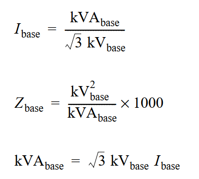
Associated with each impedance element and its kVA base, is a line-to-line kV base (usually the nominal line voltage). Nominal voltage along with the resulting base impedance and base current related by the following expressions:

Three Phase Network

three phase network

Single Phase Network

Single phase netword

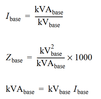
Note: Each of the above relationships involving kVAbase are sometimes expressed in terms of the corresponding MVAbase, where MVAbase = kVAbase/1000.

This results in the convenient expression of (KV2base/MVAbase) for Zbase for both three-phase and single-phase networks.

Sample Calculation

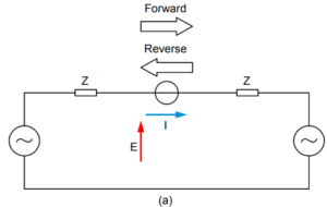
Below example/figure illustrates the use of the per-unit method:

Classical Ohmic Presentation
Figure (a): Classical Ohmic Presentation
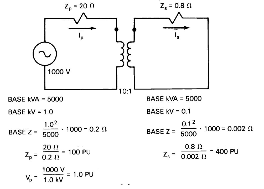
  • Step-1: The first step in a per-unit calculation is the arbitrary selection of the system base kVA
  • Step-2: The choice of base kV must be made at one voltage level from which the base value at the other voltage level is dictated by the turns ratios of the transformers.

For circuit in Figure (a), 5000 kVA and 1.0 kV are the base values on the primary of the 10:1 transformer. The resultant base voltage on the secondary of the transformer is 1.0 kV/10 or 0.1 kV.

Next step is to calculate the base impedance (primary and secondary levels) and the per-unit values of the primary and secondary impedances.

Below Figure (b) shows the simplified circuit, once the per-unit impedance and excitation source values are available:

per unit presentation
Figure (b): Per-Unit Presentation

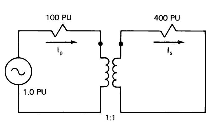
A key advantage of the per-unit method, the transformer turns ratio becomes 1:1. This removes the turns ratio from the calculations as modelled and shown below in Figure (c):

Simplified Per-Unit Representation
Figure (c): Simplified Per-Unit Representation

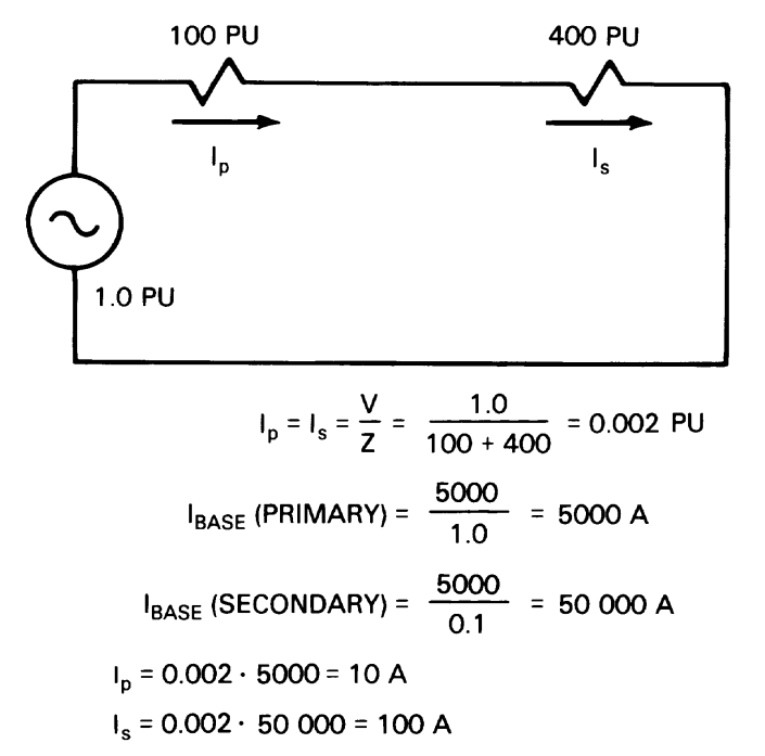
Working with the circuit in Figure (c), the primary current (Ip) and secondary current (Is) are the same. Ohm’s law can easily calculate the primary and secondary current.

The last step is to determine the actual current (Amp) by multiplying each per-unit value by the base current on the primary and secondary levels.

Although the per-unit values calculated for Ip and Is are equal, the base currents are different. Therefore the solutions expressed in amperes are different.

The basis of per-unit method of calculation is on the existence of linearity.

Relevant Contents

https://en.wikipedia.org/wiki/Per-unit_system

Related Posts

Electrical Equipment
Chief Editor

Selection of NGR (Neutral Grounding Resistor)

Selection of NGR mainly depends on key factors such as the voltage rating, the time rating and the let-through-current rating. Voltage Rating An NGR must be rated for system line-to-neutral voltage—the voltage across the resistor when a single-phase bolted ground

Read More »
protection coordination
ETAP
Chief Editor

Protection and Coordination Analysis

This article demonstrates the high level step by step procedure to perform the protection and coordination analysis in ETAP software. Below are the steps: Select protective devices models from editor Once the single line diagram and data entry is complete

Read More »
directional protection
Protection
Chief Editor

Directional Overcurrent Protection

Application Directional Overcurrent Protection is useful for all network components in which the direction of flow of power is likely to change, notably in the instance of a short circuit between phases or of an earthing fault (single phase fault).

Read More »
arc flash
Arc Flash
Chief Editor

Arc Flash Mitigation With Maintenance Mode

Introduction To Maintenance Mode The Arc Flash Mitigation with Maintenance Mode provides a method to reduce clearing time of arc flash energy. A circuit breaker equipped with Maintenance Mode can improve safety by providing a simple and reliable method to

Read More »
Tur-Gov
Electrical Equipment
Chief Editor

Generator Turbine Governor Control

Introduction The generator turbine governor control regulates rotational speed in response to changing load conditions. The governor output signal manipulates the position of a steam inlet valve or nozzles which in turn regulates the steam flow to the turbine. Turbine-generator

Read More »
Digsilent Power Flow Analysis
DIgSILENT
Chief Editor

DIgSILENT Load Flow Analysis

This article shows the step by step process on how to run DIgSILENT Load Flow Analysis. This will help engineers to practice on how to run load flow analysis on DIgSILENT Power Factory Software. Sample Network Model You can setup

Read More »

Author Information

Comments

Leave a Reply

Your email address will not be published. Required fields are marked *