Causes of Phase Voltage Unbalance
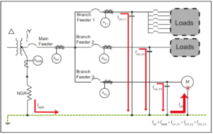
Most utilities use four-wire grounded-wye distribution systems. This is to connect single-phase distribution transformers to phase-to-neutral to supply single-phase loads, such as residences and street lights.
Variations in single-phase loading cause the currents in the three-phase conductors to be different, producing different voltage drops. This causes the phase voltages to become unbalanced.
Normally the maximum phase-voltage unbalance will occur at the end of the primary distribution system. However, the actual amount will depend on how well the single-phase loads are balanced between the phases on the system.
Perfect balance can never be maintained because the loads are continually changing, causing the phase-voltage unbalance to vary continually.
Blown fuses on three-phase capacitor banks will also unbalance the load and cause phase-voltage unbalance.
Industrial plants make extensive use of 480Y/277 V utilization voltage to supply lighting loads connected phase-to-neutral. Proper balancing of single-phase loads among the three phases on both branch circuits and feeders is necessary to keep the load unbalance and the corresponding phase-voltage unbalance within reasonable limits.
How Phase Voltage Unbalanced Is Measured?
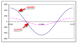
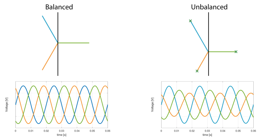
The simplest method of expressing the phase-voltage unbalance is to measure the voltages in each of the three phases.
The amount of voltage unbalance is better expressed in symmetrical components as the negative sequence component of the voltage:

Effect of Phase Voltage Unbalance
When unbalanced phase voltages are applied to three-phase motors, the phase voltage unbalance causes additional negative-sequence currents to circulate in the motor, increasing the heat losses primarily in the rotor.
The most severe condition occurs when one phase is opened and the motor runs on single-phase power.
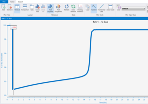
Below shows the recommended derating for motors as a function of percent phase-voltage unbalance:

Although there will generally be an increase in the motor load current when the phase voltages are unbalanced, the increase is insufficient to indicate the actual temperature rise that occurs because NEMA current-responsive thermal or magnetic overload devices only provide a trip characteristic that correlates with the motor thermal damage due to normal overload current (positive-sequence) and not negative-sequence current.
When a motor trips out, the first step in determining the cause is to check the running current after it has been restarted to make sure that the motor is not overloaded.
The next step is to measure the three-phase voltages to determine the amount of phase-voltage unbalance.
The above figure of Derating Factor Vs % Voltage Unbalance indicates that where the phase-voltage unbalance exceeds 2%, the motor is likely to become overheated if it is operating close to full load.
In general, single-phase loads should not be connected to three-phase circuits supplying equipment sensitive to phase-voltage unbalance. A separate circuit should be used to supply this equipment.