Protection and Coordination Analysis

protection coordination

This article demonstrates the high level step by step procedure to perform the protection and coordination analysis in ETAP software. Below are the steps:

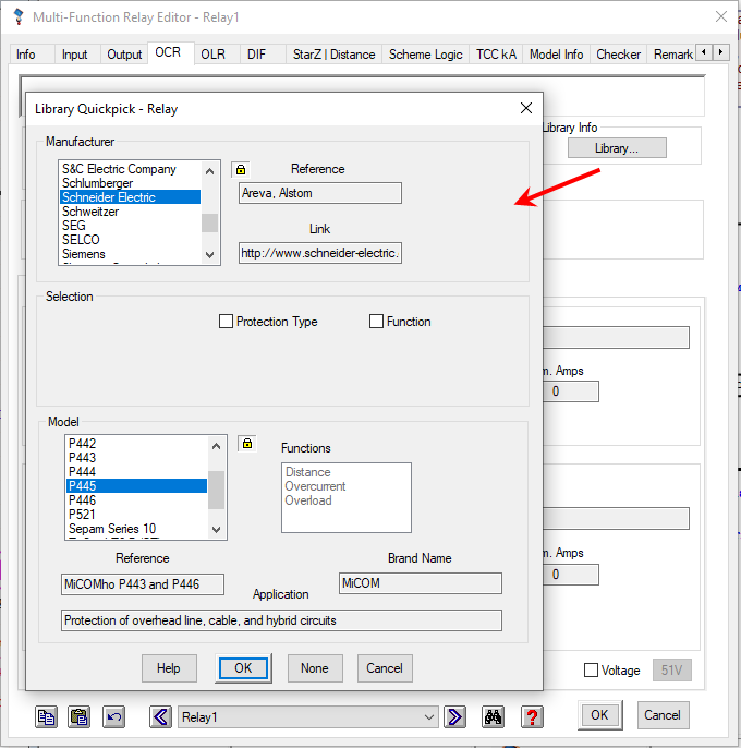
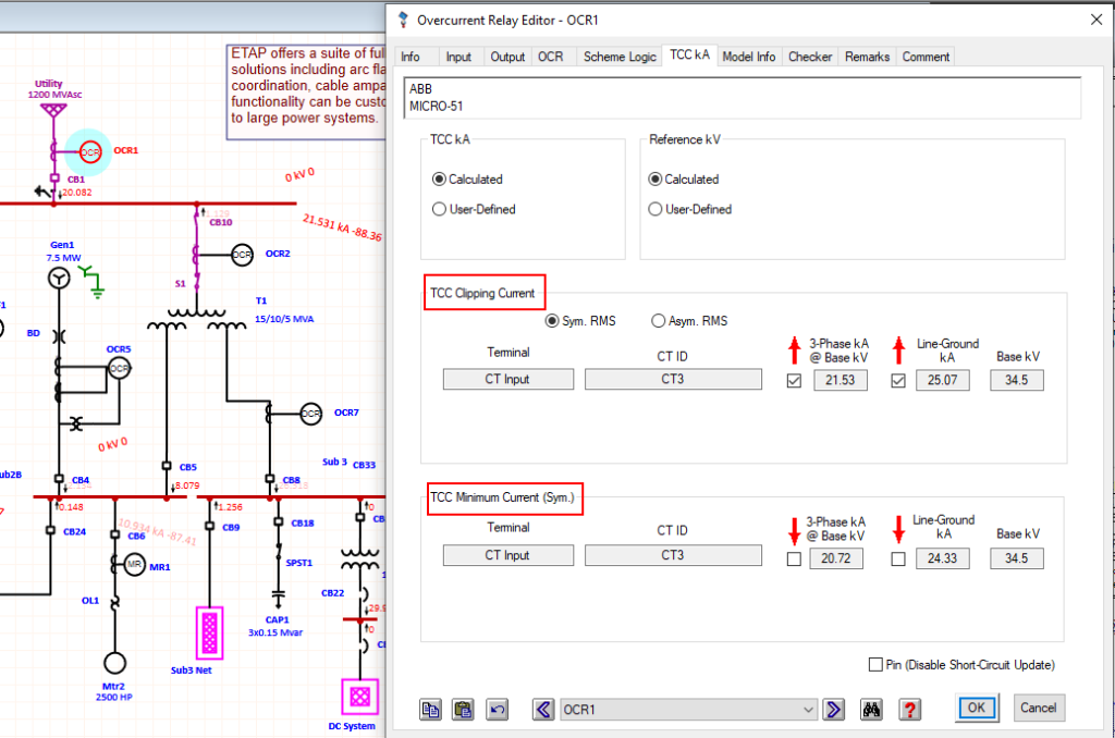
Select protective devices models from editor

Once the single line diagram and data entry is complete (including relay make/model selection), in Protective device editor, a variety of PD models can be selected from ETAP default library. Date entry is very simply in PD editors. Multiple function relay has overcurrent, overload, differential and Distance functions, directional function and 51V is also available for relay model which has these capabilities.

Select relay model in relay editor

Perform short circuit study

The fault current needs to be updated in all the protection devices using STAR module in ETAP.

Maximum and Minimum fault current updated in PD editor

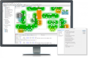
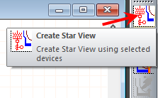
Create Star View to view protective device and equipment damage curves

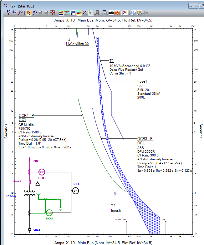
In Star Mode, create a star view by selecting devices on one line and click create star view button. In star view time current curves of protective devices (Fuse, Relay, LVCB, recloser, etc.) and equipment damages curves such as (Transformer, Cable, Transmission Line, Motor and Generator) can be easily viewed and analyzed.

Create Star View
Create Star View

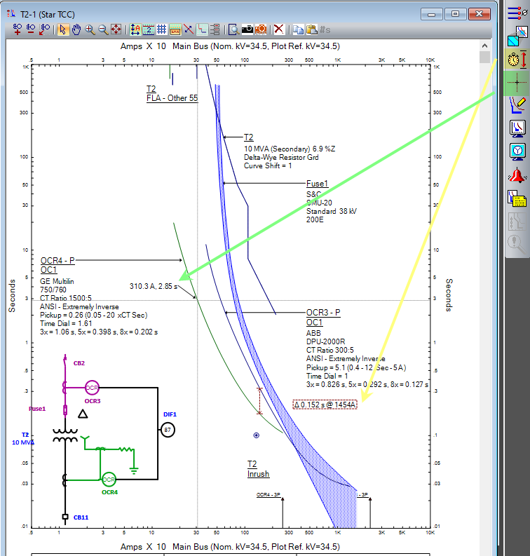
Device label setting can be displayed in star view to show the settings or parameters of the protective devices/equipment. Time current curve can be adjustable graphically or from the editor.  

Star view
Star view with fuse, relay and transformer damage curve

Tripping time or time marginal can be measured by placing a crosshair or time difference tool in star view. 

time difference tool
Time difference and crosshair tool for time margin & trip time measurement

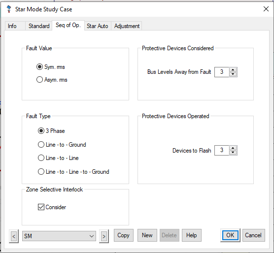
Perform Sequence of operation study

Run a Sequence of operation study to simulate a fault at any location of the system to evaluate, verify and confirm the operation and selectivity of protective devices for various type of faults directly from the one-line diagram. The operation time is calculated for each protective device based on its settings, time current characteristic, and interlocks for a specified fault location and type.

Sequence of operation study case
SQOP
Apply a 3-Ph fault at Motor IM-11 terminal

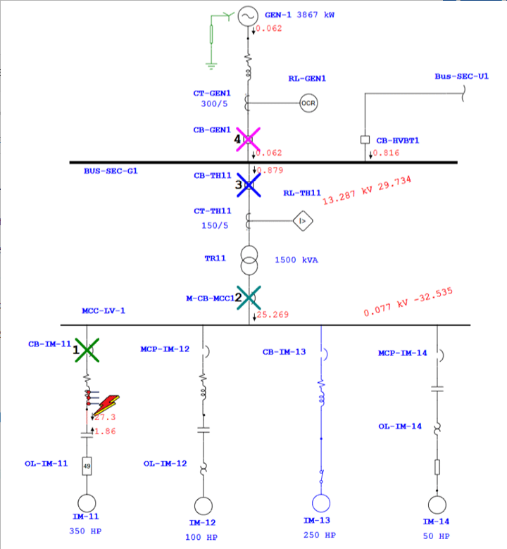
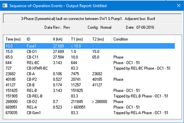
In sequence of operation, device will operate sequentially on one line, detail relay actions (27, 49, 50, 51, 51V, 59, 67, 79, 87) will be listed in Sequence of operation event viewer. 

SQOP viewer
Sequence of operation viewer

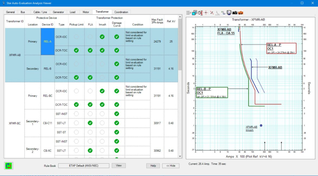
Run Star-Auto evaluation to analyze the complete system protection and coordination

By running Star-Auto evaluation, it automatic detection and evaluation of system protection and coordination / selectivity based on customized design criteria and industry guidelines. It will help to identify false tripping and miscoordination.

StarAuto Analysis Viewer
Star-Auto Analysis Viewer

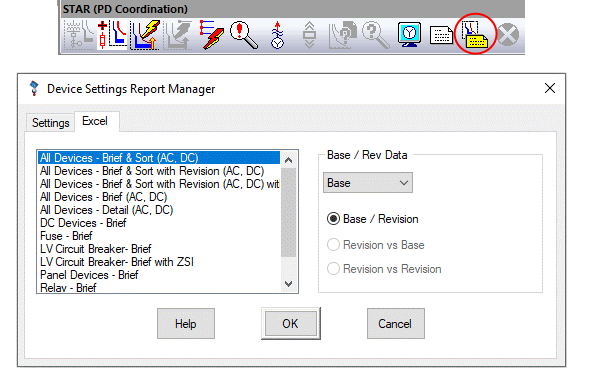
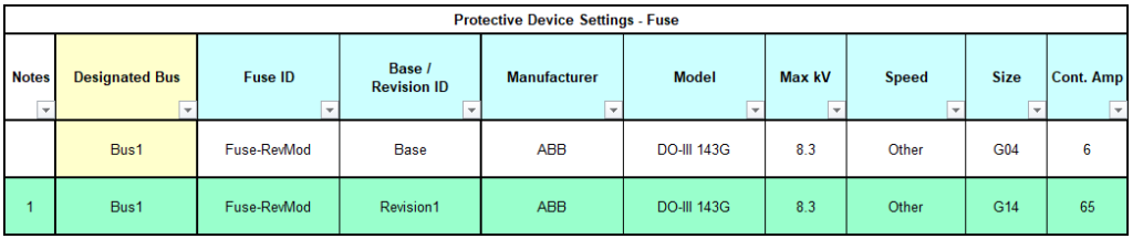
Generate protective device setting report

Generate a device setting report for all protective devices in Crystal Reports, PDF or Excel formats. Multiple templates are available for both crystal report and excel report.

Device setting report manger
Excel device setting report for fuse

Relevant Contents

Related Posts

Electrical Equipment
Chief Editor

Selection of NGR (Neutral Grounding Resistor)

Selection of NGR mainly depends on key factors such as the voltage rating, the time rating and the let-through-current rating. Voltage Rating An NGR must be rated for system line-to-neutral voltage—the voltage across the resistor when a single-phase bolted ground

Read More »
directional protection
Protection
Chief Editor

Directional Overcurrent Protection

Application Directional Overcurrent Protection is useful for all network components in which the direction of flow of power is likely to change, notably in the instance of a short circuit between phases or of an earthing fault (single phase fault).

Read More »
arc flash
Arc Flash
Chief Editor

Arc Flash Mitigation With Maintenance Mode

Introduction To Maintenance Mode The Arc Flash Mitigation with Maintenance Mode provides a method to reduce clearing time of arc flash energy. A circuit breaker equipped with Maintenance Mode can improve safety by providing a simple and reliable method to

Read More »
Tur-Gov
Electrical Equipment
Chief Editor

Generator Turbine Governor Control

Introduction The generator turbine governor control regulates rotational speed in response to changing load conditions. The governor output signal manipulates the position of a steam inlet valve or nozzles which in turn regulates the steam flow to the turbine. Turbine-generator

Read More »
Digsilent Power Flow Analysis
DIgSILENT
Chief Editor

DIgSILENT Load Flow Analysis

This article shows the step by step process on how to run DIgSILENT Load Flow Analysis. This will help engineers to practice on how to run load flow analysis on DIgSILENT Power Factory Software. Sample Network Model You can setup

Read More »
PV inverter
General
Chief Editor

Inverter Controls in AC Microgrids

Inverter controls in AC microgrid allows delivering distributed power and providing grid support services during regular operation of the grid. It also allows the powering isolated islands in case of faults/contingencies to increase the performance and reliability of electrical system.

Read More »

Author Information

Comments

Leave a Reply

Your email address will not be published. Required fields are marked *