Selection of NGR mainly depends on key factors such as the voltage rating, the time rating and the let-through-current rating.
Voltage Rating
An NGR must be rated for system line-to-neutral voltage—the voltage across the resistor when a single-phase bolted ground fault is present.
Time Rating
A resistance-grounded power-distribution system can be configured to trip, or to alarm, on the occurrence of a ground fault. An NGR dissipates P=I2R (or P=IV) power, in the form of heat, for the duration of a ground fault and must be able to do so, repeatedly, for its time rating.
For tripping systems, which rapidly de-energize a faulted circuit, a 10-second-rated NGR is typically recommended; 30- and 60-second variants are also available. For alarm-only systems (and hybrid systems that trip on a second-phase-to-ground fault), the NGR must have a continuous time rating.
Let-Through-Current Consideration (INGR)
Minimum Let-Through-Current for System Voltage Stability (INGR_min)
To eliminate the possibility of a transient-overvoltage condition, the NGR let-through-current rating must be equal to or greater than system charging current.
System charging current can be conservatively estimated to be 0.5 A per MVA for low-voltage power-distribution systems and 1 A per MVA for medium-voltage systems. However, more-accurate estimates for existing or planned systems can be made using data tables that show charging current per unit length for cables, and for transformers, rotating machines, and capacitor banks.
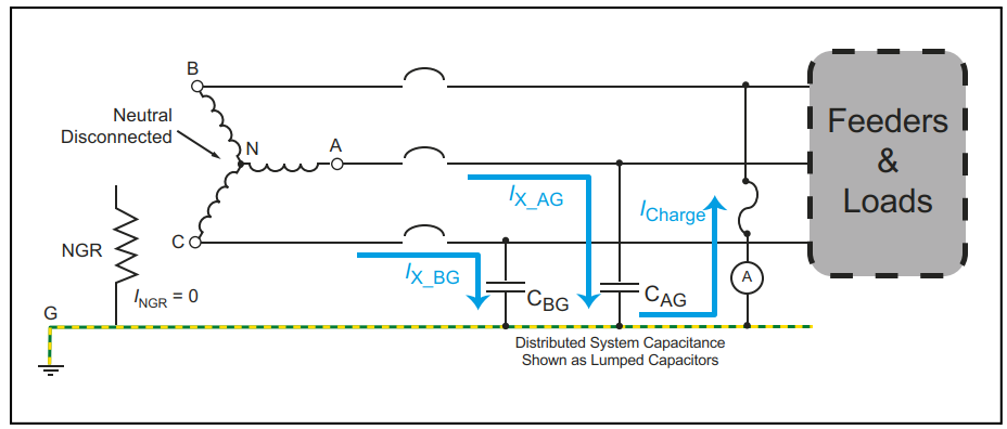
For an existing system, charging current can be measured: De-energize the system supply transformer and open its neutral-to-ground connection. Connect a phase to ground through an appropriate ammeter (and a fuse). Energize the system and bring all loads on line. System charging current will be indicated by the ammeter. System charging current changes when loads are switched and when the system size is changed by adding or removing lengths of cable (Refer below figure).
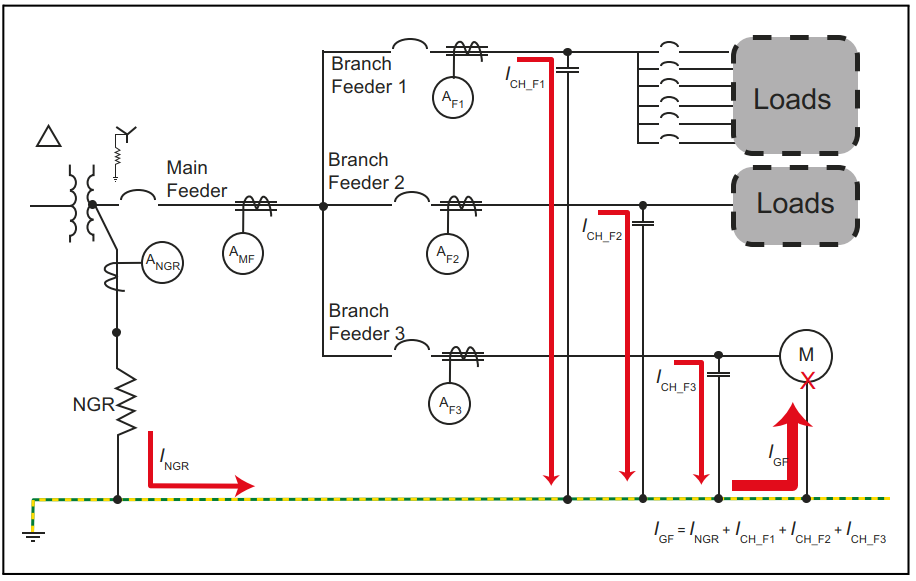
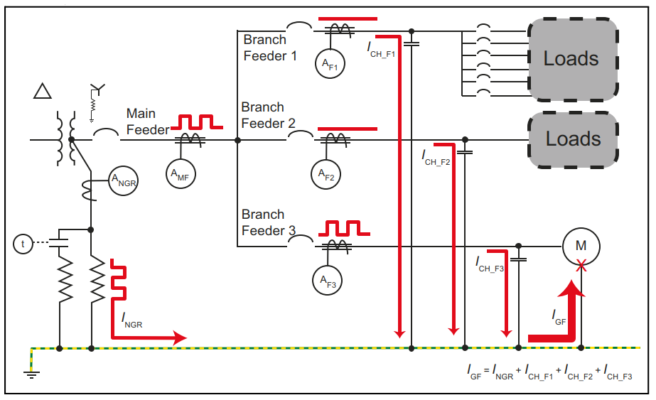
When an NGR with the minimum INGR_min current rating is used, ground-fault location and selective coordination are difficult to achieve. In a multi-feeder system with a ground fault present, a zero-sequence current transformer (ZSCT) (or a clip-on ammeter) monitoring a non-faulted feeder will indicate the charging current of that feeder, while a ZSCT on the faulted feeder detects the vector sum of the non-faulted-feeders’ charging currents and the NGR current. These values (faulted feeder vs non-faulted feeder) can be similar in magnitude, resulting in unreliable fault location or isolation. (Refer below figure)
Pulsing Ground-Fault-Location Method
A pulsing ground-fault-location system can provide assistance in locating a ground fault on an alarm-only system, especially where the INGR rating is close to INGR_min. The pulsing system, when activated, periodically changes the INGR rating, typically by adding a second, parallel, NGR, resulting in a square-wave “pulsing” current characteristic. This characteristic is readily discernable by permanently installed ZSCT’s (connected to ground-fault monitors or ammeters) or by a hand-held ammeter equipped with a clip-on CT or flexible current probe. The pulsing characteristic is indicated when the ZSCT is on the faulted feeder and upstream (line side) of the fault. (Refer below figure)
Why Select an NGR Let-Through-Current Above Charging Current?
Selective Coordination
For tripping systems in which it is desired to isolate faulted equipment while allowing the rest of the system to remain energized, ground-fault protection at the feeder or load level can detect the fault and automatically open the associated circuit breaker, contactor, or motor starter to isolate the faulted circuit. The ground-fault monitor typically uses a ZSCT as a sensor, and can be a stand-alone unit, a multi-feeder ground-fault monitor, or integrated into a multi-function feeder- or motor-protection relay. A power-distribution system can use a combination of these devices.
To ensure that a ground-fault relay does not nuisance trip or false alarm when an upstream ground fault (such as on a different feeder) occurs, choose a ground-fault-monitor trip setting that is higher than the monitored load’s charging current. A useful guideline is to choose this setting to be above the largest-feeder charging current, for all devices.
Detecting a High-Impedance Ground Fault
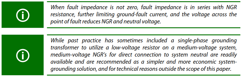
Not all ground faults are bolted faults. Fault impedance in series with NGR resistance can limit IGF to a value that is lower than the ground-fault-monitor detection setting, especially when INGR is near INGR_min. Ground-fault current below the detection setting will not be detected.
To illustrate; a ground fault at a motor terminal can be a bolted fault and result in the expected ground-fault current. However, a ground fault in the motor winding will be subject to motor-winding impedance, further limiting IGF. To detect a ground fault in 80 % of a machine winding, the ground-fault-monitor detection setting must be no more than 20 % of INGR, which requires INGR to be at least five times the ground-fault detection setting. This is a tripping ratio of 5.
An adequate tripping ratio simultaneously provides ease of ground-fault location, selective coordination, and the ability to detect a high-impedance ground fault. A minimum tripping ratio is required by some codes and standards.
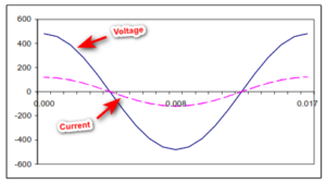
Harmonic Effects
The operation of non-linear loads in a power system creates harmonic line-to-ground voltages. Because capacitive reactance is inversely proportional to frequency (XC = ½ πfC), current per unit voltage is higher at higher frequencies. This can be an important consideration for the selection of a ground-fault monitor and its detection setting, for NGR let-through-current selection—charging current will be higher, and for the NGR time rating—ground-leakage current will be higher than it would be for a system with only power-frequency loads.
Ground-fault detection devices have a frequency response determined by their design—choose devices that are appropriate for the monitored system. In a system with possible high harmonic content, it is prudent to use at least one device, installed to monitor system neutral current, that is capable of detecting a non-fundamental-frequency ground fault.
NGR Monitoring
A grounded system uses zero-sequence-current monitoring to detect ground faults.
An NGR is a resistor that dissipates I2R heat for the duration of a ground fault, as well as the heat that results from ground-leakage current whenever the system is operating. Thermally induced mechanical stresses along with the possible presence of corrosive atmospheres (salt, H2S) and high humidity can lead to NGR failure. NGR enclosures are typically ventilated to allow convective cooling, and are often located outdoors, allowing the ingress of wind-blown dust, rain, and snow. Mechanical vibration and wildlife (rodents, snakes, birds) are also known causes of NGR failure.
An open NGR leaves the power system ungrounded—no zero-sequence current will flow when a ground fault occurs and it will remain undetected unless remedial measures are used. To mitigate this possibility, continuous NGR monitoring should be included in every NGR application.
A properly designed NGR monitor will detect NGR failure in an energized or de-energized system, with or without a ground fault present; it will detect a ground fault with or without a healthy NGR in the system, providing backup or primary ground-fault detection; and it will alarm or trip the system as necessary.