Shift Factors in Protection and Coordination Study

ETAP protection and coordination

Introduction

This article helps you to understand, how shift factors are considered and applied while performing protection and coordination study. This article mentions about applying shift factor for Line-to-Ground (L-G) fault on transformer secondary side. To understand the shift factor requirements for various other types of faults , IEEE-242 can be referred.

The per-unit currents in two phases of the transformer primary are only 58% (1/√3) of the secondary fault current. This is applicable for a Line-To-Ground (L-G) fault on a solidly grounded transformer secondary.

The primary protection relay characteristic should be shifted to the right or the transformer damage curve should be shifted to the left by 58%.

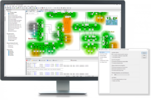
Right side image shows the transformer damage curve shift to the left by 58%. Similarly, transformer primary side protection relay characteristics can be shifted to right by 58%.

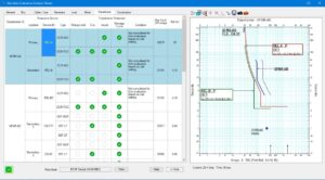
Hence, in Time Current Characteristics (TCC), Ground protection element of transformer secondary and Phase protection element of transformer primary should be coordinated at Line-to-Ground (LG) fault current on transformer secondary side. After that, shift factor shall be applied as explain above.

In summary, shift factor application in Time Current Characteristics (TCC) helps engineers to coordinate two protection relays at the same fault current.

Relevant Contents

Related Posts

Electrical Equipment
Chief Editor

Selection of NGR (Neutral Grounding Resistor)

Selection of NGR mainly depends on key factors such as the voltage rating, the time rating and the let-through-current rating. Voltage Rating An NGR must be rated for system line-to-neutral voltage—the voltage across the resistor when a single-phase bolted ground

Read More »
protection coordination
ETAP
Chief Editor

Protection and Coordination Analysis

This article demonstrates the high level step by step procedure to perform the protection and coordination analysis in ETAP software. Below are the steps: Select protective devices models from editor Once the single line diagram and data entry is complete

Read More »
directional protection
Protection
Chief Editor

Directional Overcurrent Protection

Application Directional Overcurrent Protection is useful for all network components in which the direction of flow of power is likely to change, notably in the instance of a short circuit between phases or of an earthing fault (single phase fault).

Read More »
arc flash
Arc Flash
Chief Editor

Arc Flash Mitigation With Maintenance Mode

Introduction To Maintenance Mode The Arc Flash Mitigation with Maintenance Mode provides a method to reduce clearing time of arc flash energy. A circuit breaker equipped with Maintenance Mode can improve safety by providing a simple and reliable method to

Read More »
Tur-Gov
Electrical Equipment
Chief Editor

Generator Turbine Governor Control

Introduction The generator turbine governor control regulates rotational speed in response to changing load conditions. The governor output signal manipulates the position of a steam inlet valve or nozzles which in turn regulates the steam flow to the turbine. Turbine-generator

Read More »
Digsilent Power Flow Analysis
DIgSILENT
Chief Editor

DIgSILENT Load Flow Analysis

This article shows the step by step process on how to run DIgSILENT Load Flow Analysis. This will help engineers to practice on how to run load flow analysis on DIgSILENT Power Factory Software. Sample Network Model You can setup

Read More »

Author Information

Comments

Leave a Reply

Your email address will not be published. Required fields are marked *