Introduction
Switching of an inductive circuit deserves special attention because this operation may lead to high-voltage transients. These transients can damage the involved equipment.
Inductive loads are those components capable of generating a magnetic field and typically consist of solenoids, motors, relays, transformers, Helmholtz coils or induction coils.
This article covers the modelling and results of the inductor energizing circuit at zero and peak instant of system voltage using PSCAD-EMTDC software.
Concepts
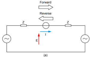
Short circuit of a passive reactor and resistor in series excited by a sinusoidal source is an important transient.
This depicts the basics of short circuit of a synchronous generator, except that the reactances of a synchronous generator are not time-invariant.
In power systems X/R ratio is high. A generator of 100 MVA, 0.85 power factor may have an X/R of 110 and a transformer of the same rating, an X/R = 45. The X/R ratios for low-voltage systems may be of the order of 2–8.
Short Circuit at Various Instant
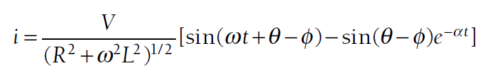
Consider that ∅ = 90°. If the short circuit occurs when the switch is closed at an instant at t = 0, θ = 0, that is, when the voltage wave is crossing through zero amplitude on X-axis, the instantaneous value of the short circuit current from ( Equation-1 ) is ( 2 x Im ). This is sometimes called the ” Doubling Effect “.
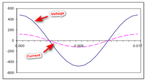
If the short circuit occurs when the switch is closed at an instant at t = 0, θ = Π /2, that is, when the voltage wave peaks, the second term in ( Equation-1 ) is zero and there is no transient as illustrated in below figure:
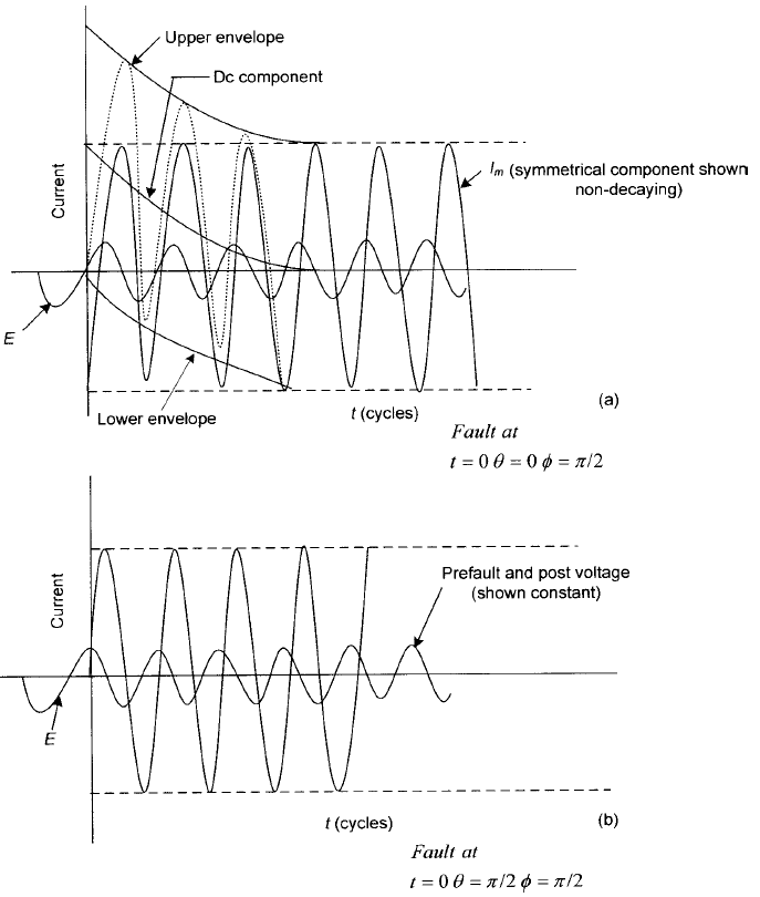
Figure-1 (b): Short circuit of a passive RL circuit on ac source, switch closed at the crest of the voltage wave.
A physical explanation of the dc transient is that the inductance component of the impedance is high.
If the short circuit occurs at the peak of the voltage, the current is zero.
When the fault occurs at an instant when θ – ∅ = 0, there has to be a transient current. The value of this transient current is equal and opposite to the instantaneous value of the ac short-circuit current.
This transient current can be called a dc component and it decays at an exponential rate. Now, further simplification of Equation (1) is as below:

Components of Short Circuit Current
This circuit transient is important in power systems from short circuit considerations. There are two distinct components of the short-circuit current:
- AC component of fault current
- Decaying DC component at an exponential rate, the initial value of the dc component being equal to the maximum value of the ac component.
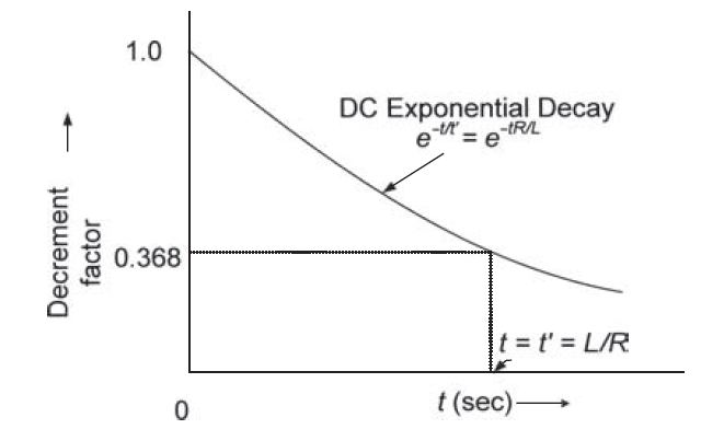
Factor L/R can be termed as a time constant. The exponential then becomes Idc x e–t/t′, where t’ = L / R.
In this equation, making t = t′, will result in approximately 62.3% decay from its original value, that is, the transient current is reduced to a value of 0.368 per unit after a elapsed time equal to the time constant as shown in below figure:
The dc component always decays to zero in a short time. Consider a modest X/R of 15; the dc component decays to 88% of its initial value in five cycles. This phenomenon is important for the rating structure of circuit breakers. Higher is the X/R ratio, slower is the decay.
Figure-1 (a) clearly shows that the presence of the dc component makes the total short-circuit current wave asymmetrical about zero line.
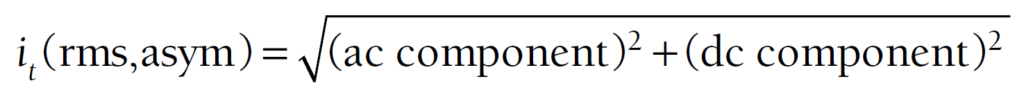
The total asymmetrical rms current:
In a three-phase system, each phase is 120° apart from each other. If a fault occurs when the dc component in phase ‘a’ is zero, the phase ‘b’ component will be positive and the phase component will be equal in magnitude but negative.
As the fault is symmetrical, Ia + Ib + Ic = 0 maintains the identity approximately.
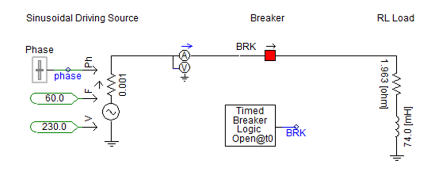
Inductor Energizing at Zero and Peak Instant of System Voltage in PSCAD
R-L Circuit Model in PSCAD-EMTDC
Summary of Results
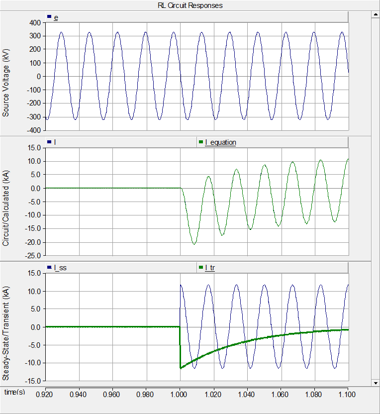
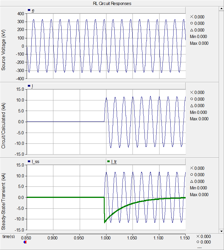
Below Figure-4 (a) and Figure-4 (b) shows the result of inductor energizing at zero & peak instant of system voltage respectively using PSCAD-EMTDC software.