
Transformer energization studies are performed to demonstrate that the resonant overvoltages are well damped and that the magnitudes do not violate temporary overvoltage capability of station equipment.
During transformer energization, two main phenomena occur: an inrush current and a voltage drop at the primary side. The amplitudes of these two phenomena depend greatly on the remanent (or residual) magnetic flux, the transformer saturation curve and the instant of energization.
Inrush Currents
Inrush current during transformer energizing is essentially an example of RL circuit switching where inductance is not linear.
If it were possible to switch ON a transformer exactly at an instant of a voltage wave which corresponds to the actual flux density in the core at that instant, it would not have resulted in any transient. In actual practice, a transient phenomenon in the form of inrush current is unavoidable due to,
- non-controllable the instant of switching easily and
- the instant of switching favorable to one phase is not favorable to other two phases.
Scenario: With Br residual flux, when the transformer energized at voltage zero instant
The purpose of this scenario is to help in understand the cause and peaky nature of inrush currents. It is assumed that the transformer which was energized earlier has been switched off at some instantaneous voltage such that the flux density is Br, which will be the residual flux. This flux density may add or subtract with the flux density that builds up when the transformer is energization later on.
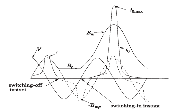
As per constant flux linkage theorem, flux density instead of starting from -Bmp (negative peak of B) varies from Br to (Br + 2 Bmp) driving core into saturation.
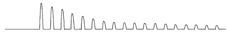
It can be observed that the current waveform is completely offset in first few cycles with wiping out of alternate half cycles because the flux density is below saturation value for these half cycles (resulting in very small current value). Hence, the inrush current is highly asymmetrical and has a predominant second harmonic component which is used by differential protection schemes to restrain relays from operating
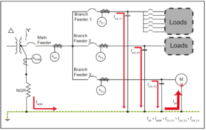
Sympathetic Inrush Currents – (Inrush in Parallel Transformers)
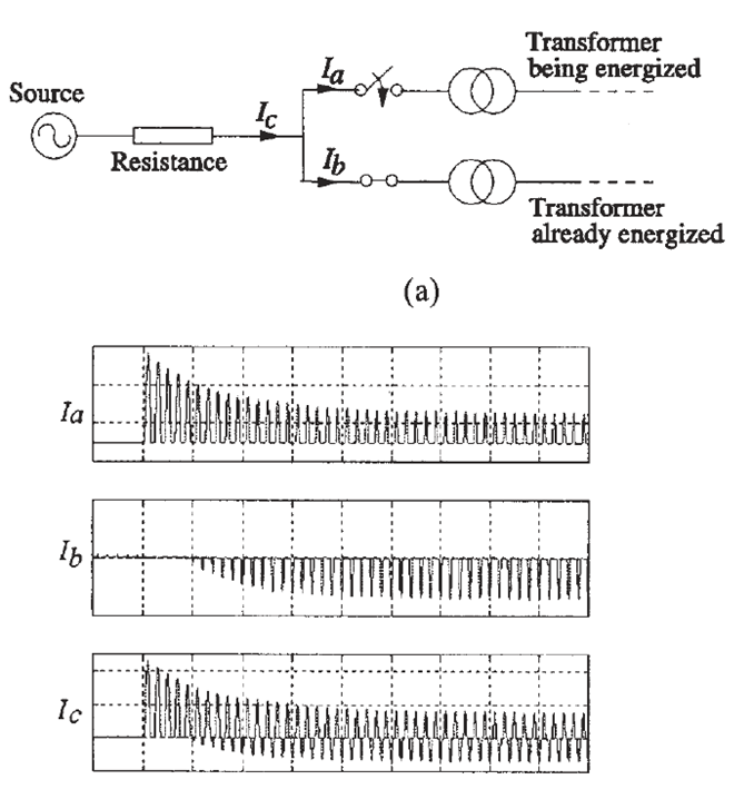
In the above figure, the transformers may or may not be paralleled on the secondary side. The DC component of inrush current of the transformer being energized (Ia) flows through the transmission line resistance (between source and transformer) producing a DC voltage drop across it.
The DC voltage drop forces the already energized transformer towards/into saturation in opposite direction of the transformer which is being switched on, resulting in a build-up of magnetizing current in the already energized transformer.
Certainly, higher source impedance (weak system) would worsen the effect of both direct and indirect (sympathetic) inrush currents.
The voltage dip due to the inrush currents with minimum and maximum SCMVA configuration of the grid / source are observed. Check with acceptable standards for voltage dips on the specified voltage buses. RMS voltage dip should not be higher than 10% at no load of transformer (this limit is minimum as compared to most industry specific standards).
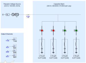
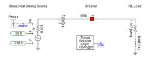
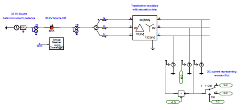
Transformer Energization Model in PSCAD
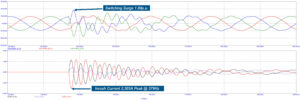
Result of Transformer Energization Study
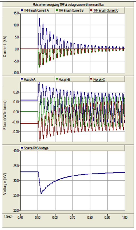
A. Results of transformer inrush current, flux, & source, RMS voltage when energized at voltage zero
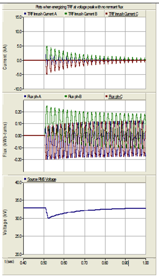
B. Results of transformer inrush current, flux, & source, RMS voltage when energized at voltage peak
Conclusion
The results of the above switching transient study show that transformer energization is sensitive to
- the point of switching
- the residual flux in the transformer core and
- the saturation knee point.
In this aspect, it can be concluded that
- When energizing transformer at zero point of voltage wave (current peak) with maximum possible residual flux,
- the magnetizing inrush current drawn is seen to be highest with corresponding bus voltage dip also high.
- When energizing transformer at peak of voltage wave (current zero) with no residual flux (even with saturation),
- the magnetizing inrush current drawn is seen to be lowest with very low bus voltage dip.