
Introduction
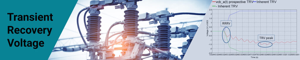
Transient Recovery Voltage (TRV)
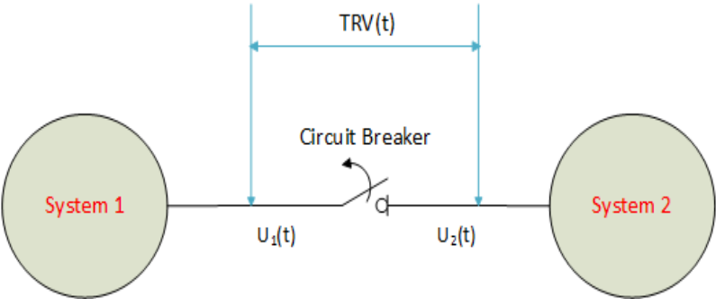
As per IEEE C37.011, “TRV is the voltage difference between the breaker terminals immediately after the current interruption of the breaker”.
It is simply the difference in the power system response voltages on the source side and on the load side of the circuit breaker.
Rate of Rise of Recovery Voltage (RRRV)
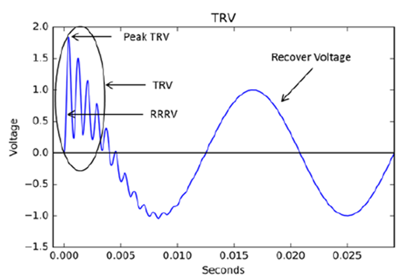
RRRV: Peak transient recovery voltage divided by the total time from zero voltage to peak voltage. Level of TRV and the RRRV are key factors in determining whether the fault can be cleared successfully.
The voltage across the breaker may be considered in two successive time intervals: one during which transient recovery voltage (TRV) exists where high frequency oscillations are observed, followed by second during which recovery voltage exists where power-frequency oscillations are observed (transient has decayed).
Purpose of TRV Study
The purpose of TRV study is to verify that the transient voltage experienced by the breaker during current interruption is within the capability of the breaker under worst-case scenarios.
The nature of TRV depends on nature of the interrupted circuit.
- LRC circuit behavior
- Travelling waves in lines
Modelling Requirements
System modelling plays an important role in carrying out the TRV and RRRV studies. As the TRV is a ‘fast event’ (10s of kHz), the system must be modelled for frequencies ranging from the fundamental to few kilohertz (kHz). For the most part, and especially for conductors requires frequency-dependent modelling.
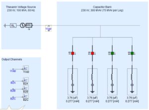
TRV is mainly due to an oscillatory transient. L and C components of the circuit determines the frequency and magnitude of the transient. Circuit components of the station has a major impact of TRV (bushing capacitances of equipment). So, it is important to represent station equipment layout/capacitances for TRV studies.
First Pole To Clear
The three poles (of breaker) do not break the current at the same instant due to 120-degree phase shift on the 3 phases.
- First pole to clear typically has the worst TRV
- Grounding conditions have an impact (grounded/ungrounded)
Standards Covering TRV Analysis
- IEEE C37.011-2011: IEEE Guide for the Application of Transient Recovery Voltage for AC High-Voltage Circuit Breaker
- IEEE C37.06-2009: IEEE Standard for AC High-Voltage Circuit Breakers Rated on a Symmetrical Current Basis – Preferred Ratings and Related Required Capabilities for Voltages Above 1000.
- IEC 62271-100: High-Voltage switchgear and control gear – Part 100: Alternating-current circuit-breaker. Edition 2.0, 2008-04
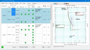
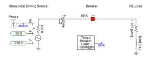
TRV Study Example
Below is the example illustrating the TRV studies. From the below graph, the TRV for breaker is exceeding the withstand capability of circuit breaker’s capability provided by the vendor in the form of family of curves. If specific capability curves are not available from vendor, IEC 62271-100 provides the required information.


One Response
Transient recovery voltage and transient restriking voltage and active recovery voltage. This three terms are same or different. Pls tell me sir and if you have formula for this then provide me.