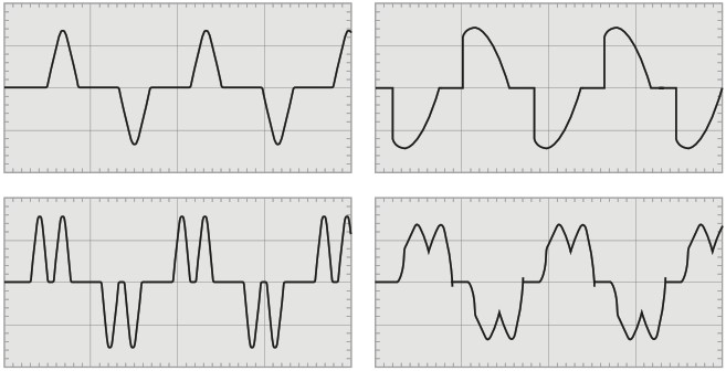
The understanding of harmonics and their origin in electrical systems is important to analyze current and voltage distortion and deviation from sinusoidal waveforms.
“Harmonic currents are caused by non-linear loads connected to the distribution system. A load is said to be non-linear when the current it draws does not have the same waveform as the supply voltage. The flow of harmonic currents through system impedances in turn creates voltage harmonics, which distort the supply voltage.”
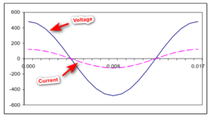
Below figure shows an example of a current wave affected by harmonic distortion on a 50Hz electrical distribution system. The distorted signal is the sum of a number of superimposed harmonics:
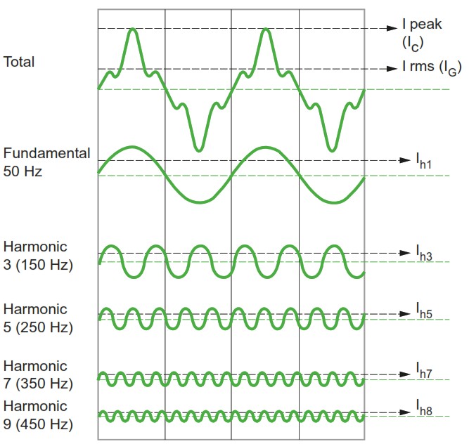
Individual harmonic component (component of order h)
The individual harmonic component is the percentage of harmonics for order h with respect to the fundamental.
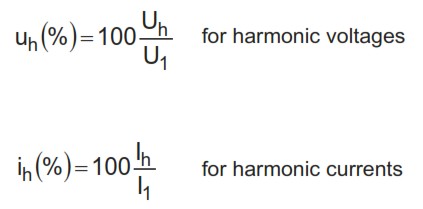
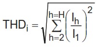
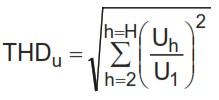
Total Harmonic Distortion (THD)
The Total Harmonic Distortion (THD) is an indicator of the distortion of a signal.
For a signal y, the THD is defined as:
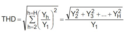
- THD is the ratio of the r.m.s. value of all the harmonic components of the signal y, to the fundamental Y1
- H is generally taken equal to 50, but can be limited in most cases to 25.
- THD is generally expressed as a percentage.
Current or Voltage THD
For current harmonics, the equation is:
For voltage harmonics, the equation is:
Origin of Harmonics
Harmonic Currents
Equipment comprising power electronics circuits are typical non-linear loads and generate harmonic currents. Such loads are increasingly frequent in all industrial, commercial and residential installations and their percentage in overall electrical consumption is growing steadily.
Examples include:
- Industrial equipment (welding machines, arc and induction furnaces, battery chargers)
- Variable Speed Drives for AC or DC motors
- Uninterruptible Power Supplies
- Office equipment (PCs, printers, servers, etc.)
- Household appliances (TV sets, microwave ovens, fluorescent lighting, light dimmers)
Harmonic Voltages
In order to understand the origin of harmonic voltages, let’s consider the simplified diagram as shown below:
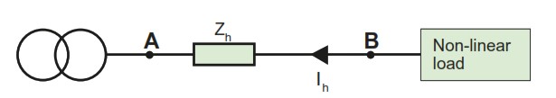
The reactance of a conductor increases as a function of the frequency of the current flowing through the conductor. For each harmonic current (order h), there is therefore an impedance Zh in the supply circuit.
The total system can be split into different circuits:
- One circuit representing the flow of current at the fundamental frequency,
- One circuit representing the flow of harmonic currents.
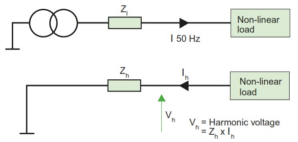
When the harmonic current of order h flows through impedance Zh, it creates a harmonic voltage Uh, where Uh = Zh x Ih (by Ohm’s law). The voltage at point B is therefore distorted. All devices supplied via point B receive a distorted voltage.
For a given harmonic current, the voltage distortion is proportional to the impedance in the distribution network.
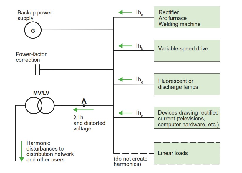
Flow of Harmonic Currents in Distribution Networks
The non-linear loads can be considered to inject the harmonic currents upstream into the distribution network, towards the source. The harmonic currents generated by the different loads sum up at the busbar level creating the harmonic distortion.
Because of the different technologies of loads, harmonic currents of the same order are generally not in phase.
Relevant Contents
https://powerworldacademy.com/causes-and-impact-of-power-quality-problems/
https://www.salicru.com/files/pagina/72/278/jn004a01_whitepaper-armonics_(1).pdf


One Response
Thanks