
This article covers the introduction of voltage drop causes and effect with calculation example of voltage drop. It is very important to understand the causes and effect of voltage drop which may occur due to certain parameters such as resistance/impedance, loading, length of the circuit etc.
What is a Voltage Drop ?
Voltage drop is the decrease of electrical potential along the path of a current flowing in an electrical circuit.
Voltage drops in the internal resistance of the source, across conductors are undesirable because some of the energy supplied is dissipated.
The voltage drop across the electrical load is proportional to the power available to be converted in that load to some other useful form of energy.
When receiving end voltage of transmission line or motor/transformer/distribution feeder is less than sending end voltage, then voltage drop occurs in the circuit.
Difference Between Voltage Drop and Voltage Sag/Voltage Dip
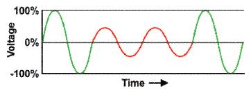
As it can be observed from above graph, there is a voltage variation for short amount of time in the middle zone which is called voltage dip phenomena.
Voltage Sag or Voltage Dip (IEC terminology) is defined by the IEEE 1159 (IEEE Recommended Practice for Monitoring Electric Power Quality) as:
“the decrease in the RMS voltage level to 10% – 90% (1% – 90% for EN 50160) of nominal voltage, at the power frequency for durations of ½ cycle to one (1) minute. It is a short duration voltage variation phenomena”.
Where as, voltage drop can last for longer duration of time than voltage dip.
Below subsequent clauses cover the causes and effect of voltage drop:
Causes of Voltage Drop
- High resistance
- Heavy load current
- Longer distance between source and load
Voltage drop in general is calculated from Ohm’s law where V = I x Z:
where, V – Voltage, I – Current and Z – Impedance
In purely resistive circuits, Z = R and thus as value of R increases, voltage drop also increases.
Also, resistance being temperature dependent, there is effect of temperature also on voltage drop. It depends on the temperature coefficient of the device across which the voltage is being dropped, and the behavior of other devices in the circuit.
In case of positive temperature coefficient, then the voltage drop across that resistance will increase with an increase in temperature. It of course also assumes the circuit under consideration is being supplied by a constant voltage which is ideal condition.
Overload also causes voltage drop. When the circuit or the total load, that the wire is providing the current, draws more current and thus the voltage drops down.
Hence proper sizing of cables is important for ensuring adequate performance of system.
Effect of Voltage Drop
- Motors unable to start — Appliances that require higher inrush current levels may not start up as the voltage is below their minimum operating power level. Torque is proportional to square of voltage and hence as voltage is below acceptable value, motor is not able to develop sufficient torque during start up.
- Inconsistent lighting levels — Street lighting design must take into account the gradual reduction in voltage level as a 5% drop in voltage can be noticeable on lighting levels.
- Blown Fuses & Tripping Circuit Breakers — Remember that P=VI so if V is low, an appliance may increase its I to reach its desired power level. When multiple loads on a circuit increase their current consumption, it could cause the safety mechanism to trip.
- Increased current consumption may cause motors and ballasts to overheat and reduce their operating life. Resistive loads such as heaters & incandescent lights will also have a reduced life span. Fluctuating voltage levels caused by other loads on the system may cause an annoying flicker.
Voltage Drop Formula
In case of non resistive three phase loads, voltage drop is calculated from approximate equations as:
Voltage Drop = √3 x I x (Rcosθ + Xsinθ)
In case of single phase loads,
Voltage Drop = 2 x I x (Rcosθ + Xsinθ)
where R – Resistance of circuit, X – Reactance of circuit, cosθ – Power factor of load, sinθ – Reactive component of load
In case of cables, multiplying above formula by length and dividing by total number of runs can give voltage drop across length of cable.
Allowable Limits of Voltage Drop Per International Standards
IEC 60364-5-52 Standard
| Type of Installation | Lighting Loads (%) | Other Loads (%) |
| Low voltage installations supplied directly from a public low voltage distribution system | 3 | 5 |
| Low voltage installation supplied from private LV supply (Note-1) | 6 | 8 |
NEC Standard
Maximum combined voltage drop for both the feeder and branch circuit shouldn’t exceed 5%, and the maximum on the feeder or branch circuit shouldn’t exceed 3%
For cable supplying motor loads, starting V.D limit is usually taken as 15% and steady state V.D. is 5%
Example – Cable Voltage Drop Calculation (From MCC to ID Fan Motor)
Given data :
Motor rating – 75 kW
Starting method – Direct On-Line (DOL)
Motor FLA (I1) – 137A
Motor Starting current (I2) – 822 A ( approximately six (6) times of FLA )
Voltage rating – 415V
System frequency – 50 Hz
Cable type and size – 1R x 3C x 120 sq.mm, XLPE Al.
Power factor cosθ1 during running – 0.9
Power factor cosθ2 during starting – 0.3
Reactive factor sinθ1 during running – 0.435
Reactive factor sinθ2 during starting – 0.953
Cable resistance (R) (at 900 ) – 0.324 Ω/ km
Cable reactance (X) – 0.0712 Ω/ km
Length of cable (L) – 140m
Solution:
Substituting values in voltage drop formula,
Steady state Voltage Drop =√3 x I1 x (Rcosθ1 + Xsinθ1) x L / (1000 x No. of cable runs)
= 10.72 V
% Steady state Voltage Drop = 10.72/415 = 2.5 %
Similarly,
Starting Voltage Drop =√3 x I2 x (Rcosθ2 + Xsinθ2) x L / (1000 x No. of cable runs)
= 19.00 V
% Starting Voltage Drop = 19/415 = 4.5 %
It can be observed from above calculations that the voltage drop during steady state and starting condition are within limits of 5% and 15% respectively.
Hence, it is safe to conclude that selected cable size/parameters are adequate for given motor.


2 Responses
Very nice presentation.Very useful topic.
Mr. Ramaswamy, thanks for your valuable feedback..