This article discusses about the importance of X/R ratio in low voltage short circuit studies.
Introduction
In some short circuit studies, the X/R ratio is ignored when comparing the short circuit rating of the equipment to the available fault current at the equipment. What is not always realized is that when low voltage gear is tested, it is tested at a certain X/R ratio.
The X/R ratio is important because it determines the peak asymmetrical fault current. The asymmetrical fault current can be much larger than the symmetrical fault current. The purpose of this article is to introduce such terms as the X/R ratio and asymmetrical fault current and to relate the importance of the X/R ratio to the rating of low-voltage equipment.
X/R Ratio and Asymmetrical Fault Current
As per Ohm’s Law, if the voltage remains constant and the impedance decreases, the fault current increases. This is true. However, it does not take into account the dynamics of AC electrical systems.
We must remember that a fault is a sudden event. Any time a sudden event occurs, the electrical system requires some time to adapt. Such a response is called a transient, which means that it lasts for only a short time.
In AC electrical systems, impedance has two components. The first is called reactance (X). Reactance depends on two things: (1) the inductance and (2) the frequency. Inductance reflects how hard it is to change the current. All conductors have some inductance, but a more useful example of a component having inductance is a coil of wire. Frequency is fixed at either 60 or 50Hz, depending upon where in the world the electrical system is, so the reactance is solely dependent upon the inductance.
The second component of impedance is the familiar resistance (R). Resistance is a measure of how hard it is for current to flow. When current flows through a material having resistance, heat is transferred from the material to the surroundings.
The resistance and reactance of a circuit establishes a power factor. The power factor (p.f.) is given by the following equation:
If the power factor is unity (1), then the impedance only has resistance. If the power factor is zero, then the impedance only has reactance.
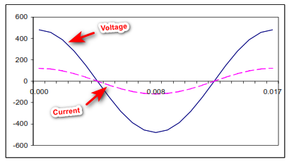
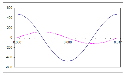
The power factor also determines how much the voltage and current waveforms (sine waves) are out of phase. Remember that both voltage and current are sine waves in linear AC electrical systems. For purely resistive systems, the voltage and current are in phase. For purely reactive systems, the voltage and current are 90-degress (one-quarter of a cycle) out of phase, with the voltage leading the current.
The above figures mean that the power factor and X/R ratio are related. Therefore, power factor and X/R ratio are different ways of saying the same thing. Please note that as power factor decreases, the X/R ratio increases.
Right after a fault occurs, the current waveform is no longer a sine wave. Instead, it can be represented by the sum of a sine wave and a decaying exponential as below:
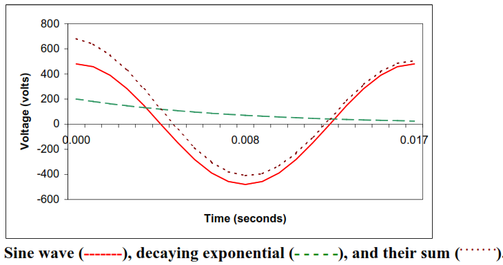
Please note that the decaying exponential added to the sine wave causes the current to reach a much larger value than that of the sine wave alone. The waveform that equals the sum of the sine wave and the decaying exponential is called the asymmetrical current because the waveform does not have symmetry above and below the time axis. The sine wave alone is called the symmetrical current because it does have symmetry above and below the time axis.
The actual waveform of the asymmetrical fault current is hard to predict because it depends on what time in the voltage cycle waveform the fault occurs. However, the largest asymmetrical fault current occurs when a fault happens at a point when the voltage is zero. Then, the asymmetrical fault current depends only on the X/R ratio, or power factor, and the magnitude of the symmetrical fault current.
Role of X/R Ratio when Comparing Short Circuit Ratings
Low voltage devices have one rating, as opposed to medium-voltage gear which have both a momentary and interrupting rating. This rating is reported in terms of symmetrical current. Therefore, the rating must be compared to the calculated symmetrical current.
All low voltage protective devices are tested at an X/R ratio. The X/R ratio at which a device is tested depends upon the device type.
Below table summarizes the device types and the X/R ratios at which they are tested.
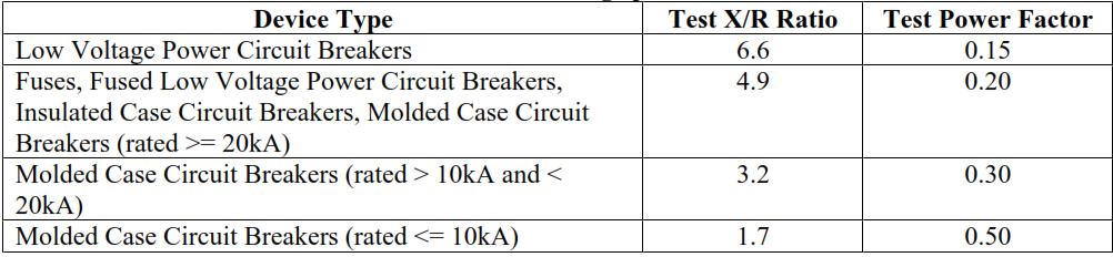
Although low voltage devices do not have asymmetrical ratings, if we know the symmetrical current rating and the test X/R ratio, then the maximum asymmetrical fault current can be easily obtained. So, in a way, there is an asymmetrical fault current rating, but it is not explicit. Therefore, in any short circuit study, both the X/R ratio and the symmetrical fault current must be taken into account.
Remember that, for a calculated value of RMS symmetrical current, as X/R ratio increase, the maximum asymmetrical current (peak or RMS) also increases.
Summary
When performing short circuit calculations, it is important to consider the X/R ratio. The higher the X/R ratio, the higher the asymmetrical peak fault current. Therefore, when verifying the ratings of electrical equipment, both the symmetrical short circuit rating and the X/R ratio must be taken into consideration.
If the calculated X/R ratio is larger than the test X/R ratio, then the equipment short circuit rating must be de-rated by a multiplying factor. This multiplying factor equals the ratio of the calculated peak asymmetrical fault current divided by the peak asymmetrical current corresponding to the rated symmetrical current and the test X/R ratio.