Zones of Power System Protection

electrical protection zones

Introduction

“Zones of protection” is one strategy which provides the level of security demanded today.

Protective relay engineers keep utility grids and equipment safe from faults and system unbalances by dividing the grid into zones.

Overlapping zones provide backup protection

To limit the extent of the power system that is disconnected when a fault occurs, protection is arranged in zones as below:

power system zones

Overlapping of Zones

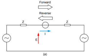
Ideally, the zones of protection should overlap. No part of the power system should remain unprotected as shown in below figure (a). Both zones include the circuit breakers.

For practical physical and economic reasons, this ideal difficult to achieve. Accommodation for current transformers in some cases are available only on one side of the circuit breakers, as shown in figure (b).

CT Location

This leaves a non-protected section between the current transformers and the circuit breaker ‘A’ against faults.

In Figure (b), a fault at F would cause the busbar protection to operate and open the circuit breaker. However, the fault may continue to be fed through the feeder.

The feeder protection, if of the unit type, would not operate, since the fault is outside its zone. Inter-tripping or some form of zone extension solved this type of problem. This is to ensure that the remote end of the feeder trips as well.

The point of connection of the protection with the power system usually defines the zone and corresponds to the location of the current transformers.

Unit type protection will result in the boundary being a clearly defined closed loop.

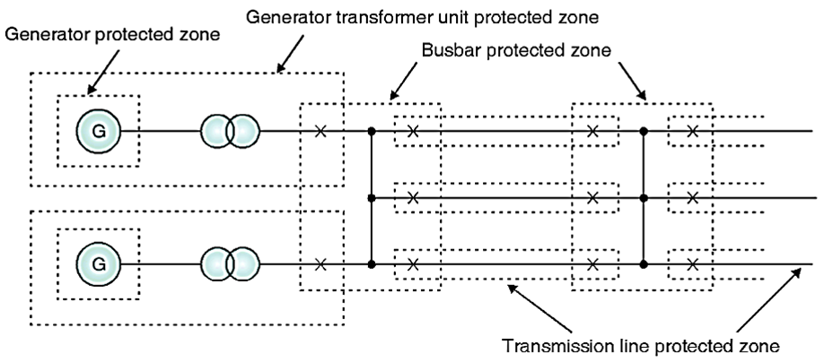
Below figure illustrates a typical arrangement of overlapping zones:

overlapping of zones

Alternatively, the zone may be unrestricted. The extent (or ‘reach’) will depend on measurement of the system quantities. Therefor, it will be subject to variation, owing to changes in system conditions and measurement errors.

Distance Protection of transmission lines applies this type of condition.

Relevant Contents

Related Posts

Electrical Equipment
Chief Editor

Selection of NGR (Neutral Grounding Resistor)

Selection of NGR mainly depends on key factors such as the voltage rating, the time rating and the let-through-current rating. Voltage Rating An NGR must be rated for system line-to-neutral voltage—the voltage across the resistor when a single-phase bolted ground

Read More »
protection coordination
ETAP
Chief Editor

Protection and Coordination Analysis

This article demonstrates the high level step by step procedure to perform the protection and coordination analysis in ETAP software. Below are the steps: Select protective devices models from editor Once the single line diagram and data entry is complete

Read More »
directional protection
Protection
Chief Editor

Directional Overcurrent Protection

Application Directional Overcurrent Protection is useful for all network components in which the direction of flow of power is likely to change, notably in the instance of a short circuit between phases or of an earthing fault (single phase fault).

Read More »
arc flash
Arc Flash
Chief Editor

Arc Flash Mitigation With Maintenance Mode

Introduction To Maintenance Mode The Arc Flash Mitigation with Maintenance Mode provides a method to reduce clearing time of arc flash energy. A circuit breaker equipped with Maintenance Mode can improve safety by providing a simple and reliable method to

Read More »
Tur-Gov
Electrical Equipment
Chief Editor

Generator Turbine Governor Control

Introduction The generator turbine governor control regulates rotational speed in response to changing load conditions. The governor output signal manipulates the position of a steam inlet valve or nozzles which in turn regulates the steam flow to the turbine. Turbine-generator

Read More »
Digsilent Power Flow Analysis
DIgSILENT
Chief Editor

DIgSILENT Load Flow Analysis

This article shows the step by step process on how to run DIgSILENT Load Flow Analysis. This will help engineers to practice on how to run load flow analysis on DIgSILENT Power Factory Software. Sample Network Model You can setup

Read More »

Author Information

Comments

Leave a Reply

Your email address will not be published. Required fields are marked *